- English
- French
- German
- Portuguese
- Spanish
- Russian
- Japanese
- Korean
- Arabic
- Greek
- German
- Turkish
- Italian
- Danish
- Romanian
- Indonesian
- Czech
- Afrikaans
- Swedish
- Polish
- Basque
- Catalan
- Esperanto
- Hindi
- Lao
- Albanian
- Amharic
- Armenian
- Azerbaijani
- Belarusian
- Bengali
- Bosnian
- Bulgarian
- Cebuano
- Chichewa
- Corsican
- Croatian
- Dutch
- Estonian
- Filipino
- Finnish
- Frisian
- Galician
- Georgian
- Gujarati
- Haitian
- Hausa
- Hawaiian
- Hebrew
- Hmong
- Hungarian
- Icelandic
- Igbo
- Javanese
- Kannada
- Kazakh
- Khmer
- Kurdish
- Kyrgyz
- Latin
- Latvian
- Lithuanian
- Luxembou..
- Macedonian
- Malagasy
- Malay
- Malayalam
- Maltese
- Maori
- Marathi
- Mongolian
- Burmese
- Nepali
- Norwegian
- Pashto
- Persian
- Punjabi
- Serbian
- Sesotho
- Sinhala
- Slovak
- Slovenian
- Somali
- Samoan
- Scots Gaelic
- Shona
- Sindhi
- Sundanese
- Swahili
- Tajik
- Tamil
- Telugu
- Thai
- Ukrainian
- Urdu
- Uzbek
- Vietnamese
- Welsh
- Xhosa
- Yiddish
- Yoruba
- Zulu
What Key Specs to Consider in a Graphic LCD Display Module for SPI Projects?
Choosing the right Graphic LCD display module board for your SPI-based embedded system can make or break the time it takes to finish the project and how well it works. Selecting a Graphic LCD display module for an SPI-based embedded product involves more than checking screen size and resolution. Integration is affected by display controller, SPI mode, maximum clock frequency, logic voltage, frame-buffer needs, backlight power, mechanical dimensions, and software support. A appropriate module should meet the end product's performance and environmental standards. Industrial HMIs, smart appliances, charging equipment, instrumentation, and other embedded systems that need PCB and firmware updates to replace displays late in development need this.SPI reduces the amount of high-speed data connections compared to parallel interfaces, making it useful for embedded screens. However, SPI bandwidth is limited. The best option depends on how much graphical data the program needs to transport, how often the screen changes, and whether peripherals share MCU resources.


Start With the Display Architecture and Application Requirements
Graphic LCD Versus Character Displays
A graphic LCD addresses individual pixels rather than displaying information through fixed character positions. This allows developers to create custom layouts containing icons, charts, logos, status indicators, images, and multilingual text.
This flexibility makes graphic displays useful for control panels and embedded instruments where the interface changes according to operating conditions. A simple thermostat may only need a few numbers and icons, while an industrial controller may need trend graphs, alarm messages, and multiple configuration screens.
Before selecting the display, define the application's actual interface requirements. The important questions include:
- How much information must be visible at one time?
- Does the application require color?
- How often does the screen update?
- Are animations required?
- Will users interact through touch?
- Does the product need a physical button or encoder?
- Is the display used indoors, outdoors, or in a controlled environment?
These requirements provide a better starting point than choosing a display based only on its advertised resolution.
When SPI Is a Suitable Display Interface
SPI's few signal lines and multiple microcontrollers make it popular in embedded devices. SCLK, MOSI, CS, and a data/command line are standard display connections. Modules may include RESET and lighting control. Some displays employ MISO for readback.
Limitations include bandwidth. High-resolution color displays need more pixel data; hence, refresh rates drop with data transmission.
For instance, a 320x240 monitor has 76,800 pixels. One 16-bit color depth frame holds 1.23 MBits of pixel data before command and communication overhead. At a theoretical 20 MHz SPI rate, pixel data transmission takes 61 ms per frame. MCU operations, including command overhead, driver behavior, DMA settings, memory access, and others, might delay performance.
SPI works well for interfaces that update individual buttons, text, or tiny screen regions. RGB or a parallel bus may be needed for frequent full-screen animation or video refreshes.
Essential Specifications for an SPI Graphic LCD
Resolution, Active Area, and Physical Dimensions
Resolution controls how many pixels are accessible for the user interface, whereas physical size dictates their appearance.
Standard embedded display formats include monochrome, 240x320 color, and 480x272 or 800x480 modules. Viewing distance, interface complexity, enclosure size, and processing resources determine the best option.
A greater resolution doesn't guarantee a better product. More pixels mean more graphical data to store and send. An excessively high resolution might affect software design if the MCU has limited RAM or the interface is bandwidth-constrained.
Be sure to verify mechanical dimensions. The diagonal dimension does not cover the installation envelope. Before freezing the enclosure design, buyers should check the active display area, bezel dimensions, PCB size, mounting holes, connection placement, and thickness.
Display Controller and SPI Compatibility
The LCD controller is one of the most important specifications for an SPI display.
The controller determines how commands, pixel data, addressing, color formats, and initialization sequences are handled. Two displays with the same resolution may use different controller ICs and therefore require different drivers.
Before purchasing samples, confirm:
- Controller IC model
- Supported SPI modes
- Maximum rated SPI clock
- Data format
- Color depth
- Command structure
- Reset requirements
- Initialization sequence
- Read/write capability
- DMA compatibility, if applicable
Do not assume that a display advertised as an SPI LCD will use the same driver as another module with an identical resolution.
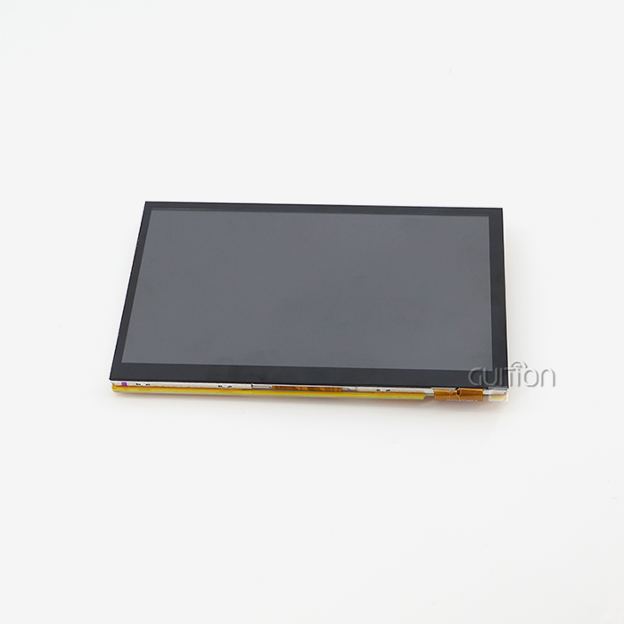
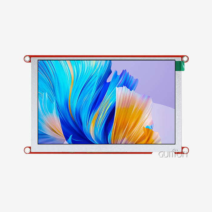
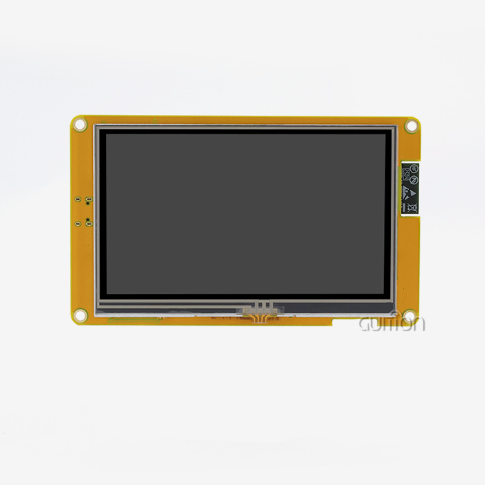
The GUITION JC8048B043N is a useful example of why model-level verification matters. Although it is a graphic display product with an 800×480 panel, its specified interface is RGB parallel rather than SPI. It therefore should not be treated as an SPI module simply because it appears in a broader comparison of Graphic LCD display module products.
Logic Voltage and Electrical Compatibility
Voltage compatibility should be confirmed before connecting the display to the host MCU.
The display's logic voltage, power input, backlight supply, and signal levels are separate considerations. A system using a 3.3 V MCU should not assume that every display input is directly compatible.
Check the module's electrical specifications for:
- Logic-high and logic-low thresholds
- Recommended supply voltage
- Absolute maximum voltage
- Backlight supply requirements
- I/O current limits
- Reset and control signal levels
If the host and display operate at different logic levels, an appropriate level-shifting solution may be necessary. The correct solution depends on the signal direction, clock speed, voltage range, and electrical characteristics of the selected components.
Assess Visual Performance for the Actual Environment
Brightness, Contrast, and Viewing Angle
Instead of a general goal number, choose brightness based on the installation circumstances.
Displays in dark appliances have different needs than control panels in bright factories. Outdoor or semi-outdoor equipment may need a brighter panel and reflection control.
Look at contrast, viewing angle, and surface treatment combined. IPS panels may have broad viewing angles, although the specification varies.
When comparing providers, request the panel datasheet rather than “wide viewing angle” or “high contrast.” Assess screens for multi-operator goods from user positions.
Color and UI Requirements
Color depth influences how graphical elements are displayed, which is relevant to: What should I look for when choosing a small LCD or TFT display module for a microcontroller project? Applications with basic status indicators may not require the same color performance as products where images, branded interfaces, or detailed visual information are central to the user experience.
The software should also be considered. A display with good panel specifications can still produce an unsatisfactory interface if the selected MCU cannot update the screen quickly enough.
For SPI designs, partial-screen updates are often useful. Updating only the area that has changed can reduce SPI traffic compared with repeatedly sending the entire frame.
Power, Temperature, and Mechanical Requirements
Backlight Power and System Consumption
System power should be calculated individually for the LCD panel and backlight.
Backlight brightness affects power consumption, especially in portable devices. Adjustable lighting settings minimize consumption when full brightness is not needed.
Engineers should measure current under intended working circumstances, not only nominal levels. If they occur simultaneously, test the display at startup, maximum brightness, constant screen updates, and wireless or peripheral activity.
Power supply margins should also accommodate transient demands. Local decoupling and PCB architecture may stabilize display connection voltage, but electrical testing should verify the final design.
Operating Temperature
The specified operating temperature should match the complete application environment.
A display used in an office appliance may operate within a relatively controlled temperature range. Industrial equipment, transportation systems, outdoor charging equipment, and unheated installations may experience much wider temperature changes.
Ask the supplier for the actual operating and storage temperature specifications of the selected model. If the application requires operation outside standard conditions, request supporting test information rather than assuming that an “industrial” product will meet the requirement.
Mechanical Installation and Connector Reliability
The connector and mounting method influence both assembly and serviceability.
FPC connections can save space, while pin headers or board-to-board connectors may be easier to handle during prototyping. The choice should reflect the final enclosure, expected vibration, assembly process, and maintenance requirements.
For production equipment, verify connector orientation, cable length, insertion direction, mounting-hole locations, PCB thickness, and clearance around the display.
Choosing Between TFT, OLED, and Other Display Technologies
TFT LCD for General-Purpose Interfaces
TFT LCDs remain a practical choice for many embedded products because they can provide color graphics, a backlight, and a wide range of sizes and resolutions.
They are suitable for applications that need menus, icons, charts, images, and status information. The main engineering considerations include backlight power, viewing angle, contrast, brightness, and the bandwidth required to update the panel.
OLED for High Contrast and Compact Designs
OLED technology produces light at the pixel level and can provide very high contrast with deep black levels. It can be useful for compact products and interfaces where visual contrast is important.
However, OLED characteristics vary considerably between panels. Brightness, lifetime, power consumption, and operating conditions should therefore be evaluated from the actual panel specification rather than generalized assumptions.
Monochrome Displays for Simple Interfaces
Monochrome graphic displays can be appropriate when the interface mainly consists of text, symbols, simple graphics, or numerical values.
They can simplify the UI and may be useful in products where cost, low power, or readability is more important than color graphics. The software design should make status information clear without depending entirely on color.
Touchscreen and Input Integration
Resistive and Capacitive Touch
Adding touch changes the electrical and mechanical design of the Graphic LCD display module system.
Resistive touch and capacitive touch use different sensing methods and controller interfaces. A capacitive touch controller commonly communicates through I2C, meaning the MCU needs another communication resource in addition to the LCD interface.
For industrial applications, touch should be tested with gloves, moisture, electrical noise, and the intended cover material where relevant. A physical button, rotary encoder, or other control can sometimes provide more predictable operation for functions that require immediate tactile feedback.
The selected display should therefore be evaluated as a complete HMI rather than simply as an LCD panel.
Supplier and Procurement Evaluation
Request Model-Level Documentation
A reliable procurement process starts with complete technical documentation.
Before placing an order, request the following information where applicable:
- Product datasheet
- LCD panel specification
- Controller IC model
- Pinout
- Mechanical drawing
- Electrical specifications
- SPI timing information
- Initialization code
- Example firmware
- Touch-controller documentation
- Recommended operating conditions
- Available compliance documents
This information allows the engineering team to verify compatibility before committing to a PCB layout.
Test Samples Under Real Conditions
Sample evaluation should reproduce the main conditions expected in the final product.
For an industrial HMI, test the display while communication interfaces and nearby electrical equipment are operating. For a portable product, measure power consumption at different brightness levels. For a charging station or outdoor installation, evaluate the display at the expected temperature and brightness conditions.
The sample should also be tested for color consistency, dead pixels, backlight uniformity, touch response if applicable, startup behavior, and communication stability.
Check Customization and Long-Term Supply
If the display will become part of a long-term product, discuss customization and component availability early.
Potential customization may include the LCD panel, touch layer, connector, PCB layout, cable, enclosure, logo, firmware, or interface configuration. The supplier should also explain how product revisions and component substitutions are handled.
Ask about MOQ, sample availability, production lead time, standard packaging, quality inspection, and technical support. These details are more useful for procurement planning than an unqualified claim that one supplier is simply “better.”
Troubleshooting Common SPI Display Problems
Flickering or Unstable Images
Flickering can have several causes, including unstable power, incorrect initialization, unsuitable SPI timing, poor signal integrity, or insufficient memory handling.
Start by checking the supply voltage at the display connector during active operation. Then verify the controller initialization sequence and SPI clock configuration. If the problem occurs only during high-speed transfers, test a lower SPI frequency to determine whether signal integrity or timing is involved.
Slow Screen Updates
Slow updates may result from excessive full-screen transfers, inefficient graphics operations, a low SPI clock, or limited MCU resources.
Partial updates are often useful because they reduce the number of pixels transferred. DMA can also reduce CPU involvement when it is supported by the MCU and driver architecture.
The correct optimization should be based on measurements rather than assumptions. Record the time required to update typical UI elements and identify whether the limitation comes from SPI transfer time, rendering, memory access, or application code.
Touch or Input Problems
For touch-enabled products, verify the controller initialization, I2C communication, calibration, interrupt configuration, and coordinate mapping.
If touch works correctly on a development board but becomes unstable in the final product, examine the PCB layout, power supply, grounding, cable routing, and nearby switching circuits.
Conclusion
An SPI project's Graphic LCD display module selection demands a full assessment of the display, controller, electrical interface, software, mechanical installation, and application environment. Resolution and screen size are only the start. LCD controller, SPI timing, logic voltage, update needs, backlight power, temperature range, and documentation may also affect integration.
When the application fits its bandwidth and pins, SPI works. Higher-bandwidth display interfaces may be better for frequent full-screen refreshes or intricate animation. The selection should be based on measurable application needs, not a generic assumption that one interface fits all products.
Verifying the model, obtaining technical documentation, testing samples with the target MCU and software, and testing the display under realistic environmental and electrical circumstances is the safest B2B procurement method. Clear requirements, sample code, customization support, consistent component sourcing, and quick engineering help decrease integration uncertainty throughout prototype development and production.
FAQ
1. What resolution should I choose for my industrial control panel?
Resolution needs depend on how much information is being shown at once and how far away the viewer is. An 800x480 screen like the GUITION JC8048B043N works well for apps that need detailed charts, status messages with more than one line, and touch button groups that can still be read from two feet away. For simple options and big numbers, lower resolutions like 320x240 are enough, which saves money and computer power for your Graphic LCD display module.
2. Can I use SPI displays for applications requiring fast animation?
Refresh rates are slower over SPI interfaces than over parallel RGB links. A 240x320 screen with 16-bit color and 10 MHz SPI updates about 8 times per second. This is fast enough for menu changes and progress bars, but not for video. Parallel interfaces, such as RGB, can support update rates of 30 fps or more, which makes them better for interfaces with a lot of motion. The GUITION JC8048B043N has an RGB parallel port, which makes it possible for dynamic user experiences with smooth motion images.
3. How do I protect my display module in harsh environments?
Graphic LCD monitor panels made for industrial use can work in temperatures ranging from -20°C to +70°C. Protect the front panel from scratches and impacts by adding chemically stronger glass or polycarbonate covers. A conformal coating on the driver PCB keeps dampness from damaging it. Choose units that are covered so that dust can't get in. The JC8048B043N is built to last and can handle the rough conditions that are common in factories and outdoor equipment setups.
Partner with Guition for Your Display Module Requirements
Picking the best provider for your Graphic LCD display module will speed up the development process and make sure that your product is successful in the long run. Guition is an expert at providing HMI display solutions that are built to last in the industrial world. Our UI development software takes away the need for complex low-level programming, and we back this up with our own unique software. Our JC8048B043N and full range of products from 1.28 to 21.5 inches give you the options you need for your projects, whether you're making smart home systems, medical devices, or charging infrastructure. Full instructions, cross-platform compatibility (including Arduino and ESP-IDF), and built-in connection through WiFi and Bluetooth modules help with secondary development. Our engineering team knows what it's like to be an embedded engineer, a product manager, or a technical founder who has to work with limited resources and tight deadlines. Contact Us at david@guition.com to talk about your application needs with a maker of Graphic LCD display modules that wants to help you succeed through quick technical support and dependable supply partnerships.
References
1. Patterson, R. & Williams, D. (2021). Embedded Display Technologies: A Practical Guide for Engineers. Technical Publishing International.
2. Chen, M. & Kumar, S. (2022). Serial Communication Protocols in Industrial Automation Systems. Journal of Embedded Systems Design, 15(3), 142-158.
3. Anderson, K. (2020). Human-Machine Interface Design for Industrial Equipment: Best Practices and Case Studies. Manufacturing Technology Press.
4. Thompson, J. & Lee, H. (2023). Display Module Selection Criteria for Medical Device Development. Biomedical Engineering Review, 8(2), 76-92.
5. Roberts, A. (2022). Power Management Techniques for Battery-Operated Embedded Systems. Embedded Computing Magazine, 19(4), 34-47.
6. Zhang, L. & Martinez, F. (2021). Quality Assurance in LCD Manufacturing: Standards and Testing Methodologies. Display Technology Quarterly, 12(1), 28-45.
Learn about our latest products and discounts through SMS or email