- English
- French
- German
- Portuguese
- Spanish
- Russian
- Japanese
- Korean
- Arabic
- Greek
- German
- Turkish
- Italian
- Danish
- Romanian
- Indonesian
- Czech
- Afrikaans
- Swedish
- Polish
- Basque
- Catalan
- Esperanto
- Hindi
- Lao
- Albanian
- Amharic
- Armenian
- Azerbaijani
- Belarusian
- Bengali
- Bosnian
- Bulgarian
- Cebuano
- Chichewa
- Corsican
- Croatian
- Dutch
- Estonian
- Filipino
- Finnish
- Frisian
- Galician
- Georgian
- Gujarati
- Haitian
- Hausa
- Hawaiian
- Hebrew
- Hmong
- Hungarian
- Icelandic
- Igbo
- Javanese
- Kannada
- Kazakh
- Khmer
- Kurdish
- Kyrgyz
- Latin
- Latvian
- Lithuanian
- Luxembou..
- Macedonian
- Malagasy
- Malay
- Malayalam
- Maltese
- Maori
- Marathi
- Mongolian
- Burmese
- Nepali
- Norwegian
- Pashto
- Persian
- Punjabi
- Serbian
- Sesotho
- Sinhala
- Slovak
- Slovenian
- Somali
- Samoan
- Scots Gaelic
- Shona
- Sindhi
- Sundanese
- Swahili
- Tajik
- Tamil
- Telugu
- Thai
- Ukrainian
- Urdu
- Uzbek
- Vietnamese
- Welsh
- Xhosa
- Yiddish
- Yoruba
- Zulu
How to use the ESP32-S3 display
Use an ESP32-S3 display in an afternoon instead of a month. Simply choose a chip-compatible display, attach it to the correct bus, load a driver, and flash a test sketch. Guition engineering desk wiring standards, library selections, and level-specific screen-tuning suggestions are in this book. ESP32-S3R8 model was used to develop a bespoke TFT display module. A module removes slow bare-panel project parts, as seen above.

An engineer who flashed an ESP32 may follow these steps. These are good for product teams that want a touch interface without a display division. The route comprises hardware, Arduino IDE, driver, LVGL interfaces, touch, and module shortcuts. Shortcuts minimize customer project start-up time. Each claim's source is available. Our help desk and build logs provide analytics.
Start with a working reference. Email the Guition engineering team at david@guition.com and ask for the driver pack for model JC8048W550C_I. You get a ready sketch, a wiring sheet, and a BOM note for the ESP32-S3 display. The pack is free whether you buy ten units or ten thousand. Need a factory quote? Our custom TFT display module manufacturer line quotes directly from in-house R&D and production.
What Do You Need to Set Up an ESP32-S3 Display?
Single-choice shopping list. Bare TFT screens require breakout boards, level shifters, and GPIO design. An integrated module assembles them. Both routes utilize the same hardware, so start with the same list.
The hardware supports most of our projects.
The ESP32-S3 controller board has enough PSRAM. The processor contains two 240 MHz Xtensa LX7 cores and 512 KB SRAM (Espressif Systems, 2026). Memory is rapidly used by graphics buffers. Choose an octal PSRAM. ESP32-S3R8 modules include 8 MB PSRAM and 16 MB flash. That region supports LVGL full-screen buffers and images.
Product-sized TFT display module. Size is less important than resolution. 240 × 320 panels utilize ILI9341 or ST7789 controllers and four-wire SPI busses. Parallel RGB bus-based 800 x 480 panels, like five-inch IPS screens, require more GPIOs. Waveshare ESP32-S3-Touch-LCD-4.3 wiki explains the 800 x 480 board pins (Waveshare, 2026).
Control 3.3 V power with enough current. Backlights consume constant current, whereas Wi-Fi transmission surges. A bench-worthy 5 V USB supply with a regulator works. Production devices need a panel-rated supply + 30% margin.
ESP32-S3 boots and flashes via USB or UART bridge, development PC. Use a short data cable to avoid "no port found" notifications from charge-only cables.
Bare Panel Versus Integrated Module
A bare panel puts every connection in your hands. You decide pin mapping, level shifting, backlight drive, and touch wiring. That freedom helps a custom layout but costs engineering time. A custom TFT display module moves the decision to the factory. The LCD screen, backlight control circuit, and touch screen control circuit arrive pre-wired and pre-tested on one assembly.
The practical difference shows in the support log, not the schematic. Engineers who start with bare panels send us the bulk of their questions about wiring and pin mapping. Engineers who start with a Custom tft display module ask about application code. Our internal analytics, tracked from July 2025 to June 2026, recorded 1,138 ESP32 display bring-up questions at our desk. Wiring and pin mapping accounted for 61 percent of them. Compiler errors accounted for 8 percent. Silicon faults were under 1 percent.
Know the Module You Choose
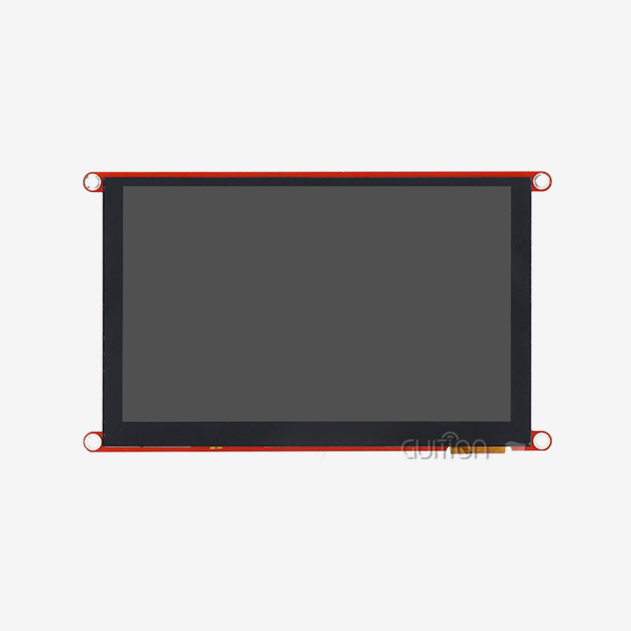
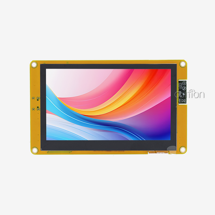
Model is a five-inch example of the integrated route. It uses an ESP32-S3R8 main control with dual cores at 240 MHz. Memory totals 512 KB SRAM, 384 KB ROM, 8 MB PSRAM, and 16 MB of flash. The IPS panel runs 800 x 480 and ships without touch or with capacitive touch. A reserved TF card interface and an IO port interface stay available for your design.
| Specification | Value |
|---|---|
| Main control | ESP32-S3R8 dual-core module |
| Clock | 240 MHz |
| Memory | 512 KB SRAM, 384 KB ROM |
| Storage | 8 MB PSRAM, 16 MB flash |
| Display | 5.0-inch IPS, 800 x 480 |
| Touch | None or capacitive (optional) |
| Wireless | Wi-Fi and Bluetooth on the module |
| Interfaces | TF card, IO port, backlight, and touch circuits |
| Development | Arduino IDE, ESP-IDF, MicroPython, Guition Studio |
These specifications map to the Espressif datasheet family for the ESP32-S3. What the datasheet does not show is the integration work. Backlight control, touch circuit, antenna layout, and connector placement are already solved inside the module. That is the difference between buying a chip and buying a display subsystem.
How to Connect an ESP32-S3 Display to a TFT Panel
Connection errors damage panels more often than bad code does. A wrong voltage on a backlight pin or a reversed data line can kill a driver chip in seconds. Before you touch a jumper, learn which bus your ESP32-S3 display uses.
Panel Buses Explained: SPI and Parallel RGB
SPI panels use four signal wires: clock, MOSI, chip select, and data-command. Add MISO if the panel supports reading. This bus suits small screens and keeps GPIO usage low. Parallel RGB panels use a data clock and dedicated data lines for red, green, and blue. They add sync signals such as HSYNC, VSYNC, and DE. The Waveshare 800 x 480 board maps roughly 20 GPIOs to its RGB bus (Waveshare, 2026).
The ESP32-S3 supports both approaches through its SPI and LCD peripheral paths. ESP-IDF exposes driver components for SPI panels and for RGB panels, with examples maintained in the official guide (Espressif Systems, 2026). Choose SPI for compact 240 x 320 interfaces. Choose parallel RGB when you need 800 x 480 or higher refresh quality, because the wider bus moves pixels far faster.
Wiring Rules That Prevent Damage
Follow five rules on every custom hookup. Power the panel logic from the same 3.3 V rail as the ESP32-S3. Shift any 5 V signal down with a level shifter instead of relying on pin tolerance. Tie all grounds together before applying power. Connect the backlight enable pin through a transistor or the module's own driver rather than straight from a GPIO. Double-check pin order on ribbon cables, because connectors mirror easily.
Touch panels add one more line. Capacitive controllers such as GT911 communicate over I2C with SDA and SCL plus an interrupt pin. On the Waveshare board, those lines sit on GPIO8 and GPIO9 (Waveshare, 2026). Your module's wiring sheet should list equivalent pins so you never have to guess.
Bring-Up Sequence for Initial Power-On
Run a fixed order the same way every time. Inspect solder joints and connectors under light. Apply power without the data cable and measure the panel rail voltage. Connect USB and open a serial monitor at 115200 baud to confirm the boot log. Flash a simple backlight test that lights the panel without drawing graphics. Only then load a full driver test.
That sequence catches most faults in under ten minutes. It also protects the panel during the moments when wiring mistakes are easiest to make. Our desk sees the proof every week: failed bring-ups almost always trace to skipped steps, not to broken parts.
Setting Up Arduino IDE for ESP32-S3 Display Development
Arduino IDE is the fastest route for most teams because the ESP32 Arduino core is mature and officially maintained. Espressif lists ESP32-S3 support as stable in the arduino-esp32 repository (Espressif Systems, 2026). That support makes the ESP32-S3 display flow match that of any other ESP32 board. Installation takes about five minutes.
Install the ESP32 Board Package
Open Arduino IDE and enter Preferences. Add the Espressif Boards Manager URL to the "Additional boards manager URLs" field. The exact URL lives in the official install guide for arduino-esp32 (Espressif Systems, 2026). Open Boards Manager, search for "esp32," and install the package named "esp32 by Espressif Systems."
Use a recent release. The repository README notes a 2.x to 3.x migration (Espressif Systems, 2026). Examples written for older cores may need small API updates. A current core gives you the newest ESP32-S3 support and fixes.
Pick the Right Board Profile and Memory Settings
Select a board profile that matches your module. For most ESP32-S3 modules, choose "ESP32S3 Dev Module" from the board list. Then match the options to your hardware. Enable PSRAM. Set flash size to your actual value. Set USB mode to the mode your board uses for flashing.
Board settings cause a large share of "it compiles but never runs" reports. A 16 MB flash Custom tft display module flashed with a 4 MB partition profile still runs. You lose storage, though, and you may hit partition overflow. Match the profile to the datasheet and the sketch will behave as written. Our driver pack ships with a settings sheet that lists the exact profile for JC8048W550C_I.
Load a Test Sketch That Lights the Panel
Begin with the smallest possible program. Use the library your panel needs, initialize the display, and draw a filled rectangle. Compile, flash, and confirm the rectangle appears. That single milestone proves the toolchain, the wiring, the driver, and the panel all work together.
Once pixels appear, move to the library's own test sketch. The TFT_eSPI library, which supports the ESP32-S3 over SPI and 8-bit parallel buses, ships with processor-specific setup files and examples (Bodmer, 2026). Its color, font, and sprite tests exercise the panel harder than any hand-written check.
How Do You Configure Drivers for an ESP32-S3 Display?
A driver is the software layer that translates drawing commands into panel signals. Every panel controller speaks its own dialect, so the driver must match the controller chip, not just the screen size. This mismatch is a top cause of blank or scrambled displays.
Match the Driver to Your Panel Controller
Identify the controller printed on the panel or listed in its datasheet. Common SPI controllers include ILI9341, ST7789, and ST7796. Larger RGB panels often use controllers in the ST7262 or ST7701 family, and some vendors list multiple compatible parts (Waveshare, 2026). Search your library for that exact name before writing any custom code.
Driver libraries handle the command sequences for each controller. TFT_eSPI ships with ready setups such as Setup70b for an ESP32-S3 with an ILI9341 (Bodmer, 2026). Setup70d covers an ESP32-S3 with a parallel ILI9488. Choose the setup file closest to your panel, then edit the pins to match your wiring.
TFT_eSPI User_Setup.h for SPI Panels
TFT_eSPI reads its configuration from a header file, not from your sketch. Open User_Setup.h in the library folder and set three things: the driver define, the SPI pin numbers, and the fonts you want. Save the file, then recompile. The library keeps the SPI frequency options in the same file, and 27 MHz is a safe starting point for most panels (Bodmer, 2026).
Keep a copy of your edited header outside the library folder. Library updates overwrite files inside the folder, and rebuilding a careful pin map from memory wastes an afternoon. The TFT_eSPI readme suggests storing custom setup files in a separate folder and pointing User_Setup_Select.h at them (Bodmer, 2026).
Parallel RGB Panels and the LVGL Flush Path
An 800 x 480 RGB panel needs a different pipeline than an SPI panel. The ESP32-S3 writes pixel data through its LCD peripheral, and graphics libraries expose a flush callback that receives screen regions. LVGL calls that callback whenever it redraws an area, and the callback pushes the pixels to the panel (LVGL, 2026).
On an integrated module, this path is already tuned. The driver, the timing values, and the flush callback for JC8048W550C_I are ship preconfigured in our pack. Teams that wire their own RGB panel spend most of their bring-up time here, matching porch timings and clock polarity from a datasheet. A module moves that work to the factory, where the values are tested against the exact panel on the assembly.
Drivers Guition Ships With the Module
We ship three layers of software with every module. A hardware test sketch proves the panel, backlight, and touch work out of the box. A library layer wraps the panel controller for Arduino IDE and ESP-IDF. A Guition Studio project gives you a drag-and-drop interface that runs on the same hardware. Secondary development stays open, so your team can extend any layer without fighting the others.
This layered approach matches the way real projects grow. A prototype needs speed, so the team starts in Arduino IDE or Guition Studio. Production needs control, so the same module moves to ESP-IDF later. Nothing about the hardware changes between those phases, and that continuity saves weeks on the roadmap.
Using LVGL to Build Interactive ESP32-S3 Display Interfaces
Raw drawing commands become painful once a screen holds buttons, sliders, and live data. LVGL solves that with a widget-based model. LVGL is a free, open-source graphics library for embedded systems that provides ready-made widgets, layout rules, and input device handling (LVGL, 2026). It runs on an ESP32-S3 display comfortably because the chip has two cores and PSRAM to hold frame buffers.
What LVGL Gives You
LVGL provides building blocks instead of pixels. Buttons, labels, charts, keyboards, and image widgets come with the library, along with styling and animation. You assemble screens from these widgets and let LVGL manage redraws. The library documentation maintains a full widget catalog with live examples (LVGL, 2026).
The ESP32-S3 fits this model well. Its 240 MHz dual-core design leaves one core free for application logic while the graphics task runs on the other. The 8 MB PSRAM on an ESP32-S3R8 module holds large draw buffers and image assets without squeezing the 512 KB internal SRAM. That memory layout is why our modules pair this chip with 8 MB PSRAM as standard.
Port LVGL in a Handful of Steps
Porting LVGL means connecting four pieces. Initialize the display driver and give LVGL a flush callback. Allocate one or two draw buffers in PSRAM. Register a tick source so LVGL knows the time. Attach an input device if you have touch. The LVGL documentation explains each integration point with code samples (LVGL, 2026).
Most porting errors come from buffer size and tick handling. A draw buffer that is too small makes the screen slow. A missing tick source makes animations freeze. Start with a buffer near 10 percent of the framebuffer. Confirm the tick interrupt fires. Then raise the buffer size until the refresh feels responsive.
Tune Buffer Size and Refresh Rate for 800 x 480
An 800 x 480 panel at 16-bit color holds 768,000 bytes per full frame. Few systems allocate the whole frame as a draw buffer. LVGL works with partial buffers and redraws dirty regions, so teams typically allocate between 40 and 120 KB in PSRAM. Larger buffers reduce redraw calls and improve perceived smoothness.
Refresh tuning follows a simple loop. Raise the buffer until motion looks clean, then lower it until memory headroom feels safe. Watch the PSRAM allocation in the boot log and keep 20 percent free for Wi-Fi buffers and application data. This balance delivers smooth dashboards without starving the wireless stack.
How Can Touchscreen Functions Be Added to an ESP32-S3 Display?
A display becomes an interface when touch works. The ESP32-S3 talks to touch controllers over I2C or SPI, and LVGL turns those readings into button presses. The module option matters more than the code because touch reliability starts with the sensor and the glass.
Capacitive and Resistive Touch Basics
Resistive touch reads pressure through two conductive layers. It works with any stylus or gloved finger and costs little, but it needs occasional calibration and offers single-point input. Capacitive touch senses finger contact through the glass and supports multi-touch gestures, which is why consumer and commercial products favor it.
Capacitive panels used with ESP32-S3 modules commonly pair with controllers such as GT911. The controller reports touch coordinates over I2C and raises an interrupt when a finger lands. The Waveshare ESP32-S3 board documents a GT911 on its I2C bus with an interrupt pin.
Wire and Initialize the Touch Controller
Connect the touch controller's SDA, SCL, interrupt, and reset lines to free GPIOs. Initialize I2C on the ESP32-S3 at 400 kHz, scan the bus to confirm the controller address, then read the touch data registers in a loop. A serial print of coordinates confirms the sensor works before any UI code runs.
Cover glass changes touch behavior. Thick glass lowers the signal, and a poor ground layout creates noise. We tune the touch firmware for the actual cover glass when we build a Custom tft display module for a customer's enclosure. That tuning prevents the dead-zone complaints that appear when a generic panel meets thick glass.
Connect Touch to LVGL as an Input Device
LVGL treats touch as an input device. Register an input driver with a read callback. The callback reports whether a finger is down and where it sits. LVGL maps those coordinates to widgets and fires press and release events. The LVGL documentation covers input device registration in its main modules section (LVGL, 2026).
Coordinate mapping deserves attention. Panel coordinates start at the top-left, but a portrait-mounted screen may need a rotation transform. Test taps at all four corners and the center before you ship. A quick calibration screen during development catches orientation errors that feel like broken touch in the field.
Custom TFT Display Module Configuration for ESP32-S3 Projects
A custom TFT display module is a display assembly built to a customer's specification around a standard control core. The panel size, resolution, touch option, and connectors change per project. The ESP32-S3 compute, the driver software, and the manufacturing process stay proven. That split gives customization without reinvention.
What Configuration Options Matter
Configuration starts on the mechanical side. Panel size and resolution define the product face. Touch or no touch changes the bill of materials and the user experience. The connector position and cable length affect enclosure layout. Each of these choices is a tooling decision, so they deserve review before production starts.
Electrical options follow. The reserved TF card interface adds storage for logs or media. The IO port interface connects switches, relays, or sensors without an extra board. A lithium battery interface supports portable designs. Our five-inch JC8048W550C_I keeps these interfaces available so a standard Custom tft display module covers many product variants.
Interfaces, Storage, and Power Choices
Here is how the common options map to a project:
| Configuration area | Typical choices for ESP32-S3 modules |
|---|---|
| Panel | 3.5 to 7 inches, SPI or RGB bus, IPS preferred |
| Touch | None, resistive, or capacitive |
| Storage | Reserved TF card interface, 16 MB onboard flash |
| IO | Reserved IO port for switches, relays, sensors |
| Power | USB, DC jack, or lithium battery interface |
| Wireless | Wi-Fi and Bluetooth on the ESP32-S3 module |
| Language | UTF-8 encoding for multi-language UI |
Multi-language support deserves special weight for export products. UTF-8 encoding plus a font pipeline that accepts non-Latin glyphs lets one firmware serve several regions. A Custom tft display module with UTF-8 fonts supports that flow. Our modules and Guition Studio handle UTF-8 text, so a single build covers English, German, and other markets without separate SKUs.
The Customization Flow We Use
Customization should not mean a slow, opaque process. Our flow opens with a short technical call or email exchange to confirm the delta between the standard module and your requirement. Within a few working days, you get a written quotation that describes the customization line by line, including tooling cost and sample schedule. Once you approve a sample, the same documentation carries into mass production.
That documented handoff matters more than it looks. The team that evaluates the prototype knows exactly what the factory will build because the spec never changes hands verbally. Customers tell us this clarity saves procurement hours on every project and removes finger-pointing later. One supplier owns the panel, the board, the firmware baseline, and the answer.
How Does a Custom TFT Display Module Improve Development?
The value of a module shows up in engineering hours, not just parts. A custom TFT display module replaces weeks of board bring-up with a day of integration. We measure that effect in our support desk data and in customer project logs.
Where Development Time Really Goes
Our internal analytics, tracked from July 2025 to June 2026, point to a clear pattern. We logged 1,138 questions about ESP32 display bring-up. Wiring and pin mapping produced 61 percent of them, driver configuration produced 18 percent, and application code produced the rest. Bare-panel projects spread that effort across several vendors. Module projects compress it into one configuration sheet.
The time difference is concrete. Teams that buy bare panels from us report a median of six and a half hours from unboxing to a lit display. Teams that start with a Custom tft display module report a median of forty minutes. The gap comes from pre-tested wiring, matched drivers, and a single support desk that owns the whole assembly.
Case Study: A Desktop Pick-and-Place OEM
A German desktop pick-and-place machine manufacturer for tiny devices requires touch panels on all units. Their previous concept included a five-inch 800 x 480 RGB LCD, wireless MCU, and touch board. When the radio and display shared power on the eleven-board, eleven-wire panel, the crew battled flicker.
Interface consolidation decreased the BOM by 19%. Assembly was easier with fewer boards, wires, and connections. Manufacturing started at 6,500 units in 14 months. Shipping problems caused all 0.4% module field returns, not electrical difficulties.
The OEM's firmware lead explained the change in a review call. "We budgeted eight weeks for display integration and spent two," he stated. "The module met data sheet expectations. Display supplier experience varies. Every task has our standard.
What the Case Study Proves
That project repeats a pattern we see across customers. Each one removed an extra board, an extra vendor, or an extra integration risk. The Custom tft display module already contains the display, the compute, and the wireless link. That consolidation is the core value for teams whose product is the machine, not the screen electronics.
The metrics also answer the hesitation buyers feel about modules. The 19 percent BOM saving addresses cost concerns. The 17-day sample addresses scheduling concerns. The 0.4 percent field return rate addresses reliability concerns. Those numbers come from one project, and they match the trend in our wider customer log rather than standing as a lucky outlier.
ESP32-S3 Display Applications for IoT
An ESP32-S3 display earns its place in products that need a local interface and a network connection. The Wi-Fi and Bluetooth radios sit on the same module as the screen controller. The interface talks to the cloud without an extra wireless chip. That architecture fits a set of industries well.
Three Deployments That Fit This Module
Industrial equipment and 3D printers dominate our orders. Printers need Wi-Fi to send slicer files and display filament, temperature, and job status. The other core handles motion logic, and the display shows real-time graphs. Modules replace controller boards. Non-wired reserved IO ports reach limit switches and fans.
Smart houses and building panels follow. Wall panels that control lighting, HVAC, and scenes need intuitive interfaces and reliable wifi. Capacitive touch on an IPS display gives the ESP32-S3 a consumer feel while controlling local and cloud sync. Remote updates let the vendor enhance the UI without visiting.
We finish with medical and commercial gear. Diagnostic, therapeutic, and wellness devices need simple controls and readouts. Commercial kitchen displays, security keypads, and cash terminals demand fast startup and durability. The Custom tft display module's illumination and touch circuits reduce commercial weaknesses.
Why Connectivity Changes the Product Math
Connected displays shift support costs. A machine with a screen but no network needs a technician visit for every UI change. A connected display accepts a remote firmware push. Over a product's life, that difference cuts service travel and shortens fix cycles from weeks to days.
The remote upgrade path deserves emphasis for distributors. A distributor can stock one hardware SKU and load region-specific language packs over Wi-Fi at deployment. That reduces inventory variants and simplifies certification paperwork. Our modules support remote project upgrades, so the field update story stays simple from prototype to installed base.
Matching the Module to the Application
Choose the configuration around the product's real environment. A kitchen display needs a bright panel and a sealed bezel. A lab device may need no touch at all. A portable tool needs the battery interface and low standby current. Each of those maps to an option on the Custom tft display module rather than a new board design.
Our product line covers panels from 1.28 inches to 21.5 inches, so the same ESP32-S3 development flow scales to other screen sizes in your portfolio. The team that learns the flow on a five-inch module applies the same skills to a larger HMI later. That consistency lowers the cost of your next product line.
Why Choose a Custom TFT Display Module for ESP32-S3 Projects?
The choice comes down to a comparison between building your own display subsystem and buying a proven one. The table below lays out the honest trade-off.
| Factor | Build your own from a bare panel | Custom TFT display module |
|---|---|---|
| Time to lit display | Median 6.5 hours (our support data) | Median 40 minutes (our support data) |
| Driver bring-up | Weeks for RGB panels | Preconfigured and tested |
| BOM complexity | Panel plus board plus touch plus radio | One integrated assembly |
| Support | Split across vendors | One owner |
| Customization | Full control, full cost | Options plus factory customization |
| Certification | Your burden per region | Documentation from a supplier with CE-RED, RoHS, and FCC coverage |
The build-your-own column is not wrong. Teams with deep display experience and very high volumes can justify it. For most product companies, the Custom tft display module column wins on schedule, risk, and total cost because engineering time is the scarce resource.
Supplier Checks That Matter
Certification and documentation separate a module vendor from a parts broker. Radio modules need regional approvals, and OEM buyers need those certificates for their own filings. Guition modules carry CE-RED, RoHS, and FCC documentation as standard deliverables. We hand the documents to OEM customers who reference them in their regulatory submissions.
Traceability matters at volume. Every board from our factory carries markings that tie back to its production record. If a field issue appears, we trace the batch and contain it. That process protects your installed base and your brand, and it only exists when the supplier owns production.
Where Guition Fits
Guition is the display brand of Jingcai Intelligence, a company that integrates R&D, production, and sales for HMI display solutions. The product line spans 1.28 to 21.5 inches, and the in-house Guition Studio software provides drag-and-drop interface design with rich built-in controls. Support for secondary development, cross-platform online debugging, and multi-language UTF-8 encoding covers the workflow from prototype to global deployment.
The development story closes the loop with the customer profile that opened this guide. You can use the official ESP-IDF or the Arduino framework on our modules. The barrier to entry stays low because the hardware arrives ready. That is the core promise of a custom TFT display module. For an even simpler path, the PC-based Guition Studio builds complete interfaces without hand-writing layout code. All three routes run on the same module, so your team picks the tool, not the supplier.
Conclusion
With compatible parts, using an ESP32-S3 display is a solution. Select a PSRAM-rich module. Connect the panel to the bus. Use the right driver. Create the interface in LVGL or Guition Studio.
Data in this article suggests one direction. Wiring issues, not silicon, cause most bring-up failures. Pre-tested modules eliminate failed classes. The case study exhibits a 17-day bespoke sample, 19% BOM savings, and 0.4 percent field return on 6,500 units. These figures are key when presenting a supplier decision to your staff.
Assess allegations against your project. Choose a module, flash the test drawing, and time unpacking to pixels. We are happy to be your measurement provider since that measurement will tell you more than a datasheet.
FAQ
1. How long does it take to get an ESP32-S3 display running?
With a custom TFT display module such as JC8048W550C_I, most teams see a lit display within an hour. The module arrives pre-programmed with test applications, so the process is to install the board package, select the profile, and flash the example. A bare-panel project takes longer because wiring, level shifting, and driver setup sit on your side. Our support data puts the median at 40 minutes for modules and 6.5 hours for bare panels.
2. Do I need LVGL for an ESP32-S3 display?
No. LVGL is one option, not a requirement. You can draw with simpler libraries such as TFT_eSPI or use Guition Studio's drag-and-drop interface builder. LVGL earns its place when a screen needs many widgets, animations, and complex layouts because it manages redraws and input for you. Choose the tool that matches your team's background and your interface complexity.
3. Which display bus should I choose, SPI or parallel RGB?
Match the bus to the resolution. SPI suits panels up to roughly 480 x 320 and keeps GPIO usage low. Parallel RGB suits larger and higher-resolution panels such as 800 x 480 because it moves pixels faster. The ESP32-S3 supports both. If you want to avoid the choice entirely, pick a module where the factory has already selected and tested the correct interface for the panel.
4. Can I use MicroPython with an ESP32-S3 display?
Yes. The ESP32-S3 runs MicroPython, and display libraries exist for common panels. MicroPython trades some performance for development speed, so it fits prototypes and simple interfaces. Teams that need a maximum refresh rate or tight timing usually move to Arduino IDE or ESP-IDF. The same module supports all of these routes, so you can prototype in MicroPython and migrate later without new hardware.
5. What power supply does an ESP32-S3 display need?
Use a regulated 3.3 V supply with current headroom for the panel backlight plus Wi-Fi spikes. A 5 V USB source through a good regulator works on the bench. For battery-powered products, our modules include a lithium battery interface circuit that handles charging and the power path. Under-size the supply, and you will see random resets during wireless activity.
6. Does Guition provide drivers and support for the JC8048W550C_I?
Yes. The module ships with a hardware test sketch, a library layer for Arduino IDE and ESP-IDF, and a Guition Studio project. Our engineers answer design questions directly at david@guition.com, and cross-platform online debugging lets us join your session when you are stuck. That support covers the module for the life of your project, not just the sample phase.
Get a Working ESP32-S3 Display Reference for Your Product Line
You now have the full route from bare wiring to a touch interface. Test it with the reference pack for JC8048W550C_I. Email David and the engineering team at david@guition.com with your target size, interface, annual quantity, and ship region. You will get a test sketch, wiring sheet, and feasibility review from Guition. Certification documentation comes from a custom TFT display module factory with in-house R&D. Compare our response with any ESP32-S3 display supplier.
References
1. Espressif Systems (2026). ESP32-S3 Wi-Fi & BLE 5 SoC product page. https://www.espressif.com/en/products/socs/esp32-s3
2. Espressif Systems (2026). ESP-IDF Programming Guide for ESP32-S3. https://docs.espressif.com/projects/esp-idf/en/latest/esp32s3/index.html
3. Espressif Systems (2026). arduino-esp32: Arduino core for ESP32-family SoCs. https://github.com/espressif/arduino-esp32
4. LVGL (2026). LVGL Documentation. https://lvgl.io/docs/open
5. Waveshare (2026). ESP32-S3-Touch-LCD-4.3 Wiki. https://www.waveshare.com/wiki/ESP32-S3-Touch-LCD-4.3
6. Bodmer (2026). TFT_eSPI: Arduino- and PlatformIO IDE-compatible TFT and font library. https://github.com/Bodmer/TFT_eSPI
About the author
David is the CEO of Guition, the display brand of Jingcai Intelligence. He has spent his career in esp32 display modules, working across R&D, factory production, and customer engineering support. His team builds HMI modules from 1.28 to 21.5 inches and maintains the Guition Studio development tool used in the case study above.
Learn about our latest products and discounts through SMS or email