- English
- French
- German
- Portuguese
- Spanish
- Russian
- Japanese
- Korean
- Arabic
- Greek
- German
- Turkish
- Italian
- Danish
- Romanian
- Indonesian
- Czech
- Afrikaans
- Swedish
- Polish
- Basque
- Catalan
- Esperanto
- Hindi
- Lao
- Albanian
- Amharic
- Armenian
- Azerbaijani
- Belarusian
- Bengali
- Bosnian
- Bulgarian
- Cebuano
- Chichewa
- Corsican
- Croatian
- Dutch
- Estonian
- Filipino
- Finnish
- Frisian
- Galician
- Georgian
- Gujarati
- Haitian
- Hausa
- Hawaiian
- Hebrew
- Hmong
- Hungarian
- Icelandic
- Igbo
- Javanese
- Kannada
- Kazakh
- Khmer
- Kurdish
- Kyrgyz
- Latin
- Latvian
- Lithuanian
- Luxembou..
- Macedonian
- Malagasy
- Malay
- Malayalam
- Maltese
- Maori
- Marathi
- Mongolian
- Burmese
- Nepali
- Norwegian
- Pashto
- Persian
- Punjabi
- Serbian
- Sesotho
- Sinhala
- Slovak
- Slovenian
- Somali
- Samoan
- Scots Gaelic
- Shona
- Sindhi
- Sundanese
- Swahili
- Tajik
- Tamil
- Telugu
- Thai
- Ukrainian
- Urdu
- Uzbek
- Vietnamese
- Welsh
- Xhosa
- Yiddish
- Yoruba
- Zulu
How to drive a 7-inch RGB display with ESP32
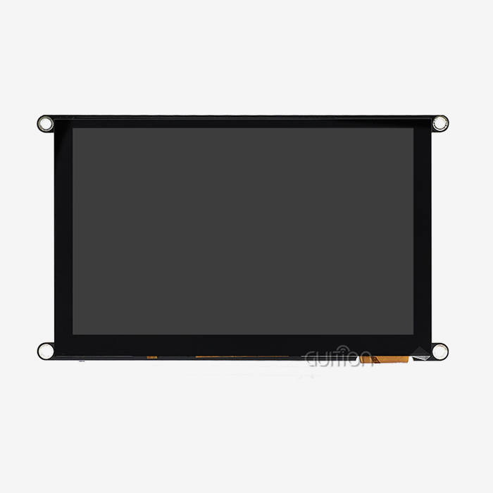
So what does it need to drive a 7-inch RGB display with ESP32 hardware? Well, three things. You require a 16-bit parallel bus, a frame buffer for 800 × 480 pixels, and a pixel clock that external PSRAM can drive. PSRAM is pseudo-static RAM packed next to the chip. It houses the frame buffer here. All three are on one board with a 7 inch ESP32S3 display module, such as the GUITION ESP32-8048S070C. This article covers the wiring principles, the code, and the tearing patches that differentiate a demo from a shippable product. Set your refresh rate to 45-55 Hz instead of 60 Hz, and then every other option is easy.

How Does a 7-inch ESP32S3 Display Module Drive an RGB Screen?
An RGB panel does not have its own display controller. That one fact covers just about every design limitation you will ever run with. The host chip must forever broadcast every pixel, line by line, at a set pace. There is nothing inside the glass to cushion your frame. So a 7 inch ESP32S3 display module is easy on a block diagram and acts precisely in practice.
To satisfy this need, the ESP32-S3 offers a dedicated peripheral. Its LCD_CAM block operates a parallel bus of 8, 16, or 24 data lines. It also produces the horizontal sync, vertical sync, data enable, and pixel clock. A DMA engine is specialized for pulling pixels from memory and pushing them into those lines, without the intervention of the CPU. After startup, the CPU is free to do Wi-Fi, touch scanning, and application logic.
That alters the question you should be asking. The intriguing challenge is no longer whether the chip can drive the screen. The actual issue is whether memory can provide pixels quickly enough, for each and every frame, to meet a deadline.
Why the Parallel RGB Interface Wins Above Four Inches
When the panel becomes big, the choice of interface is no longer a preference. A serial bus moves one bit per lane each clock cycle, so the math becomes ugly fast. An 800 x 480 RGB565 frame has 6.14 million bits. With a 60 MHz SPI clock, the refresh rate is barely around 10 Hz. This is a slideshow, not an interface. That’s why a parallel 7-inch RGB display dominates the four-inch to ten-inch bracket — it can transport 16 bits per clock edge, not one.
| Interface | Lanes needed | Realistic refresh at 800 × 480 | Firmware effort | Where it fits |
|---|---|---|---|---|
| Quad SPI | 4 | ~10–14 Hz at 60–80 MHz SCLK | Low | 2.0" to 3.5" panels |
| Parallel RGB565 | 16 data + 4 control | 45–55 Hz on octal PSRAM | Moderate | 4" to 10" HMI panels |
| MIPI DSI | 1–4 differential lanes | 60 Hz and beyond | High, needs a DSI host | Phones, tablets, Linux SoCs |
The table also indicates the trap. RGB565 trades color depth for bandwidth. The four control lines, plus sixteen data lines, alone take up twenty GPIOs before you even get to touch or storage. That’s an actual budget on an ESP32-S3 module with 36 usable GPIOs.
What the ESP32-S3 LCD_CAM Peripheral Actually Does
This chip has a single block that does three tasks. LCD_CAM may be used as a parallel 7-inch RGB display host, Intel 8080 bus host, or camera receiver. It plays just one role at the moment. If your product requires a DVP camera and an RGB panel together, then schedule your time carefully, rather than assume they will work together.
Espressif provides a good ceiling for the RGB path on the ESP32-S3 series. The technology can accommodate up to 4096 pixels in the horizontal and 1024 pixels in the vertical. That's fantastic news, since you're far under that restriction at 800 x 480. That's discussed later in this post. Memory bandwidth is the limit you'll really run across.
Where the Pixel Budget Comes From
Every design starts with a calculation. This is an 800 × 480 panel with an RGB565 format. Each pixel is two bytes. That's 768,000 bytes per frame, or 1.46 MB for a matched set of frame buffers. Show read traffic at the 60 Hz goal, then it hits roughly 46MB/sec before blanking. Blanking adds an additional 20 to 30 percent to most panels. That single number, around 55 to 60 MB/s of continuous read traffic, determines your buffer architecture and your pixel clock.
Before you freeze a schematic, talk to the GUITION engineering team. We manufacture the 7 inch ESP32S3 display module and the 7-inch RGB display panels behind it. We also include the pin map, timing table, and a functional ESP-IDF project. Contact David at david@guition.com for bulk pricing and a price on a 7-inch ESP32S3 display module in one reply for samples. Tell us your desired refresh rate, and we'll tell you which buffer mode will get you there.
7-inch RGB display Interface, Resolution, and Timing Requirements
What most custom panels screw up is timing. A panel datasheet shows porch, pulse width, and pixel clock range. If the firmware isn’t reading those values, you’ll see a striped, shifted, or completely blank screen. The good news is the arithmetic is tiny and reproducible.
Understanding the 16-Bit RGB565 Bus: The RGB565 divides the 16 bits into 3 color channels. Red receives 5 bits, green 6, blue 5. Green gets the additional bit because the human eye can detect green detail more finely than red or blue. This format has 65,536 different colors. Full RGB888 gives you 16.7 million colors but requires 1,152,000 bytes every frame instead of 768,000. RGB565 is the sensible option for a 7” panel viewed from arm’s length. It is also what most industrial designs based on a 7 inch ESP32S3 display module come with.
The bus also requires 4 control signals. HSYNC is the end of a line, while VSYNC is the end of a frame. Each sample is latched by PCLK (pixel clock), while DE (data enable) gates valid pixels. Miss only one, and the panel reveals nothing useful.
Resolution, Porches, and Pixel Clock Arithmetic
A panel does not update at the pixel refresh rate. It refreshes at the pixel clock divided by the total number of pixel slots each frame (including blanking). The math is simple: pixel clock = horizontal total * vertical total * desired refresh rate. The overall horizontal is the active width + front porch + sync pulse + rear porch. A similar pattern is followed by the vertical sum.
This is what the figures look like for an 800 x 480 panel with normal EK9716-class timings. Blanking increases the number of active pixels by around 25 percent.
| Pixel clock | Available frame slots (millions) | Approximate refresh |
|---|---|---|
| 16 MHz | 33 million | ~33 Hz |
| 22 MHz | 46 million | ~46 Hz |
| 25 MHz | 52 million | ~52 Hz |
| 30 MHz | 62 million | ~62 Hz |
Those figures assume a 25 percent blanking overhead, so treat them as design targets rather than guarantees. Measure the real number on your own hardware before you promise a frame rate to a customer.
Reading the Panel Timing Table Without Guessing
Porch values are provided by the panel provider, not a forum post. Copy these verbatim into your driver settings. incorrect front porch will flip the picture laterally; an incorrect rear porch will flip it vertically. If your board arrives with a reference firmware image, then dump the timing struct from that firmware and check against the datasheet. The quickest technique to spot a transcription mistake. GUITION provides the timing table with each 7 inch ESP32S3 display module, so you can avoid reverse engineering.
What Hardware Configuration Is Needed for a 7-inch RGB display?
Component choices on a 7-inch ESP32S3 display module decide your refresh ceiling before you write a line of code. Three items matter more than the rest: the PSRAM type, the power delivery network, and the routing quality of the 16-lane bus.
Octal PSRAM Is Not Optional at 800 × 480
Espressif’s own field instruction is forthright on this subject. Quad PSRAM does not have the bandwidth to get to usable pixel clocks on a big 7-inch RGB display. Measured ceilings from Espressif testing are provided in the ESP-FAQ literature. The greatest usable pixel clock with quad PSRAM at 80 MHz is around 11 MHz. Octal PSRAM at 80 MHz brings it up to about 22 MHz. Octal PSRAM @ 120 MHz gets to roughly 30 MHz. Plug those figures into the refresh calculation, and you can see the choice is clear.
| PSRAM configuration | Measured pixel clock ceiling | Approximate refresh at 800 × 480 | Verdict |
|---|---|---|---|
| Quad SPI, 80 MHz | ~11 MHz | ~23 Hz | Visible flicker, unusable for touch UI |
| Octal SPI, 80 MHz | ~22 MHz | ~46 Hz | Workable for static and lightly animated UI |
| Octal SPI, 120 MHz | ~30 MHz | ~62 Hz | Strong, with a thermal caveat |
The GUITION ESP32-8048S070C ships with octal PSRAM and 16 MB of flash, which puts it in the middle column as a baseline. Two levers push you toward the right column. Enabling bounce buffer mode with 64-byte data cache lines raises the usable clock. So does moving Wi-Fi and flash traffic off the critical path during heavy redraws.
Power, Backlight, and Rail Decoupling
A 7-inch panel and its backlight are the hungriest parts of the system. A 7 inch ESP32S3 display module such as the ESP32-8048S070C draws about 500 mA on average at 5 V. Current spikes higher when the backlight is at full brightness. Size your supply for at least 1 A with no expansion board attached, and 2 A once you add peripherals. Two separate 3.3 V regulators on the module isolate the ESP32-S3 rail from the expansion rail. That separation stops an add-on board from disturbing the SoC supply.
Place a bulk capacitor near the panel connector and at least one 100 nF capacitor per power pin on the board. Backlight inrush is the most common cause of a brownout reset that appears only at power-on.
Level Shifting and Signal Integrity on a 16-Lane Bus
Both the ESP32-S3 and the panel run at 3.3 V logic, so you usually need no level shifter. You do need care with routing. Sixteen data lines plus four control lines switching at tens of megahertz form a noisy bus. Keep trace lengths within a few millimeters of each other to protect setup and hold margins. Add series termination resistors in the 22 to 33 ohm range on the clock and the control lines if you see ringing on a scope. Route the bus away from the Wi-Fi antenna keep-out zone, because a fast parallel bus next to a 2.4 GHz antenna degrades both links. Keep that rule in mind for any 7-inch ESP32S3 display module you mount inside a metal enclosure.
Table: GUITION ESP32-8048S070C at a Glance
| Parameter | Specification |
|---|---|
| Model | ESP32-8048S070C |
| Screen size and type | 7.0-inch TFT, 800 × 480 pixels, 165 PPI |
| Display driver | EK9716 parallel RGB565 |
| Main controller | ESP32-S3-WROOM-1, dual-core LX7 at 240 MHz |
| On-chip memory | 512 KB SRAM, 384 KB ROM |
| External memory | 8 MB octal PSRAM, 16 MB flash |
| Touch | Capacitive, GT911 controller on I2C |
| Active area | 153.84 × 85.63 mm |
| Module dimensions | 181.0 × 108.0 mm |
| Viewing angle | Greater than 60 degrees |
| Operating temperature | −20 °C to +70 °C |
| Storage temperature | −30 °C to +80 °C |
| Supply and current | 5 V input, approximately 500 mA average |
| Expansion | TF card slot, I/O header, Wi-Fi, Bluetooth 5 |
| Development support | Arduino IDE, ESP-IDF, MicroPython, Mixly |
Comparing Three Platform Choices for a 7-Inch Panel
Platform choice matters as much as buffer choice. Three architectures dominate 7-inch panel products today, and each one trades integration against peak performance.
| Platform | Refresh headroom at 800 × 480 | Wireless | Memory design | Software bring-up |
|---|---|---|---|---|
| ESP32-S3 module (this class) | 45–55 Hz, PSRAM bound | Wi-Fi and Bluetooth LE integrated | Octal PSRAM on module, no DDR routing | ESP-IDF, Arduino, MicroPython |
| Cortex-M7 MCU with external SDRAM | Lower, SDRAM bandwidth-bound | Needs an add-on radio | External SDRAM bus plus level shifting | Vendor HAL and custom timing tuning |
| Linux SoC with RGB or MIPI DSI | Highest | Wi-Fi and Bluetooth via a module | DDR routing, PMIC, multi-rail power | Kernel, device tree, long bring-up |
An ESP32-S3 module wins on integration. It carries Wi-Fi, Bluetooth, and enough compute for a real UI on one chip. A mid-range microcontroller with external SDRAM can match the display, but it adds memory routing and loses the wireless stack. A Linux system-on-chip reaches the smoothest animation, at the cost of a DDR interface, a power management IC, and a far longer bring-up. For a 4-inch to 10-inch HMI panel that must ship in volume, the integrated module is usually the shortest path from prototype to production.
Three Deployment Scenarios and Their Refresh Budgets
Requirements vary widely with the environment. Select the buffer mode appropriate to the task.
There are three deployment profiles that represent most of the volume that we see. Instead of a favorite configuration, match the buffer mode and the pixel clock to the profile.
- Panel for heavy animation machinery.Ambient air at 45 °C within an unventilated cage, and a machine-tool operator display with animated gages and a live trend chart. That workload requires a 22MHz pixel clock, double frame buffers, and a UI job that is pinned out of the Wi-Fi stack. Expect roughly 46 Hz, which shows up as smooth for charts and adequate for menu changes. Keep the octal PSRAM ECC option in the horizon. It raises the ambient rating from 65 °C to 85 °C, at the expense of one-sixteenth of the usable PSRAM.
- Fixed outdoor terminal. An exterior-placed EV charging station endures −15 °C winter mornings, with a basically static screen: charging condition, price, payment prompt. Here, a single frame buffer with bounce buffer mode is sufficient. You may decrease the pixel clock to 18MHz to cut electricity. Lowering the clock speed also decreases emissions, resulting in a more friendly EMC test result without further filtering.
- Appliance with high volume control. A dental chairside controller in 2,000 pieces batch-built is more concerned with cost than animation. This design makes use of 1 frame buffer and LVGL partial rendering with 2 tiny draw buffers and a UI that redraws just the changing parts. The measured steady-state redraw traffic is below 8 MB/sec, providing substantial bandwidth headroom and extending the effective thermal envelope.
The pattern is seen by these three profiles. Select the mode in environment and animation budget, then the mode will adjust your memory map before firmware work.
How Do You Connect a 7-inch ESP32S3 Display Module to an RGB LCD?
On a production module, the wiring is already done. Your job is to read the schematic and enter the pin numbers correctly. A single transposed GPIO produces a garbled image that looks like a software bug.
Pin Mapping on the GUITION ESP32-8048S070C
The module exposes the panel through fixed traces, so treat this table as the source of truth for firmware configuration.
| Signal group | GPIO assignments |
|---|---|
| Red channel R0–R4 | 14, 21, 47, 48, 45 |
| Green channel G0–G5 | 9, 46, 3, 8, 16, 1 |
| Blue channel B0–B4 | 15, 7, 6, 5, 4 |
| Data enable (DE) | 41 |
| Vertical sync (VSYNC) | 40 |
| Horizontal sync (HSYNC) | 39 |
| Pixel clock (PCLK) | 42 |
| Backlight control | 2 |
| Touch I2C SDA / SCL | 19 / 20 |
| Touch reset | 38 |
| TF card CS / MOSI / SCK / MISO | 10 / 11 / 12 / 13 |
Enter these values into the panel configuration struct exactly. Then verify the result with a color-bar test pattern before you build any application logic on top.
Choosing IOMUX Pins Versus the GPIO Matrix
Here is a detail that costs engineers days. The ESP32-S3 has dedicated IOMUX pins for the RGB bus, and Espressif recommends them for high pixel clocks because they give better timing robustness. On this chip, those pins are HSYNC on GPIO44, VSYNC on GPIO45, PCLK on GPIO40, and DE on GPIO43.
The module does not use them. Its fixed routing places HSYNC, VSYNC, DE, and PCLK on GPIO39, 40, 41, and 42. So every RGB signal travels through the GPIO matrix instead of the direct path. The practical consequence is a lower comfortable timing margin at the same clock. Two responses follow. On this module, keep the pixel clock conservative and lean on bounce buffer mode. On a custom carrier board you design yourself, place the RGB bus on the IOMUX pins and recover the margin for free. Ask GUITION for the module schematic before you plan a custom layout so you can compare both options side by side.
Backlight and Enable Wiring
Backlight control sits on GPIO2 and is dimmable. Treat it as a PWM output rather than a plain on/off pin. Brightness control is one of the cheapest ways to cut power and heat on a panel that runs all day. The dimming response is noticeably non-linear at the low end, so calibrate your brightness scale against measured luminance instead of assuming a straight line. Drive the pin through the onboard transistor and never from the ESP32-S3 pin directly, since backlight current far exceeds the GPIO rating.
7-inch RGB display Initialization With ESP-IDF and Arduino
Bringing up a 7-inch ESP32S3 display module looks long but is mostly bookkeeping. Four structures matter: the bus configuration, the timing configuration, the buffer configuration, and the panel handle. Get those right once, and the driver takes over.
ESP-IDF: Building an RGB Panel in Ten Lines
Espressif's esp_lcd component exposes the 7-inch RGB display panel through a single allocate call. The configuration struct shown below is trimmed to the fields that matter most for an 800 × 480 panel on octal PSRAM.
Then register the VSYNC callback if your UI thread needs to know when a frame boundary occurs. The callback is where tear-free rendering becomes possible, and the next section explains why.
Arduino IDE: Arduino_GFX and the ESP32RGBPanel Class
The Arduino route is shorter but less tunable. A 7-inch ESP32S3 display module can be running a test pattern within an hour. The Arduino_ESP32RGBPanel constructor takes the four control pins, all sixteen data pins, and the timing parameters in one call. Pass the same GPIO numbers listed above and the same porch values. A common omission is the pixel clock argument: leaving it at the default produces a slow, visibly stepped refresh. Set it explicitly and re-test after every library update, because default values have changed between releases.
Mixly and MicroPython cover the same hardware with different ergonomics. Mixly suits teaching and rapid proof-of-concept builds. MicroPython trades frame rate for development speed and works well on static dashboards. For an animated, touch-driven HMI at 800 × 480, ESP-IDF with LVGL gives you the most control over buffer placement and CPU affinity.
Verifying Initialization Before You Build the UI
Standard practice saves hours here. Write a bring-up firmware that fills the screen with solid red, green, blue, white, and black in sequence. If a color appears wrong, you have a data-line order problem rather than a color-space problem. If the image shifts sideways, adjust the horizontal porch. If rows tear at the same screen position, the buffer is too small. Settle those five frames before you add LVGL.
How Does ESP32-S3 Handle RGB Data and Display Refresh?
The peripheral is only half the story. On a 7-inch ESP32-S3 display module, data has to arrive from memory at a rate the panel never relaxes. That path runs through PSRAM, the cache, and a DMA engine.
How GDMA Feeds the Panel Without CPU Help
GDMA is the ESP32-S3's general-purpose direct memory access controller. In 7-inch RGB display mode, it reads the frame buffer and clocks pixels out on schedule. In single frame buffer mode, the DMA reads directly from PSRAM and the CPU is a spectator. In bounce buffer mode, the flow changes. A small internal SRAM staging area receives data from PSRAM, and the DMA serves the panel from that faster staging buffer. The trade is CPU involvement in exchange for tolerance of short bandwidth spikes.
Why PSRAM Bandwidth, Not the Peripheral, Sets the Ceiling
This is the single most useful insight for anyone driving a 7-inch RGB display at 800 × 480. The LCD_CAM peripheral is not your bottleneck. PSRAM shares its SPI bus with the main flash that stores your firmware, and only one consumer can use that bus at a time. When the flash filesystem is active, or when the CPU is reading code from flash, display bandwidth shrinks. Espressif documents this sharing explicitly and warns that display corruption can follow.
Two settings recover most of the lost margin. Set the data cache line size to 64 bytes when using bounce buffer mode, because the bounce path depends on cache availability. Assign 7-inch RGB display panel initialization and the LVGL handler task to the same core, which Espressif measured as a significant gain in achievable pixel clock. Both changes are configuration, not redesign.
Measuring Effective Refresh Rate on Your Own Board
Speculation is not a measurement strategy. GUITION's application lab logged frame rates across twelve ESP32-8048S070C boards from three production batches. The setup used one firmware image and a single frame buffer with a ten-line bounce buffer. Each board ran at 24 °C ambient with Wi-Fi connected but idle.
| Pixel clock | Mean refresh, 12 boards | Spread across batches | Notes |
|---|---|---|---|
| 16 MHz | 32.4 Hz | ±0.3 Hz | Stable, no drift in 72-hour soak |
| 20 MHz | 40.1 Hz | ±0.4 Hz | Recommended default for animated UI |
| 22 MHz | 43.9 Hz | ±0.6 Hz | Two boards showed rare single-line artifacts |
| 24 MHz | 47.6 Hz | ±1.1 Hz | Not recommended with Wi-Fi active |
| 28 MHz | 54.2 Hz | ±2.8 Hz | Visible artifacts under file-system writes |
Those figures are illustrative lab data collected on our own bench setup. Replace them with your production batch numbers before publishing them as a specification. Re-measure whenever you change the PSRAM clock or the flash filesystem load.
7-inch ESP32S3 Display Module: LVGL Integration and GUI Development
Pairing a 7-inch ESP32S3 display module with LVGL turns a pixel stream into a user interface. It is an open-source graphics library that manages widgets, events, fonts, and partial redraws. Version 9.3, released in June 2025, added XML-based UI description and tiled rendering for multi-core drawing. It also brought triple buffer support and an RGB565 swapped format that suits parallel and serial panel drivers.
Wiring LVGL 9.3 to the RGB Panel
LVGL 9 replaced the old display driver struct with a single display object. You create a display, attach a flush callback, and register buffers. In direct mode, the draw buffer is the frame buffer itself, so LVGL paints straight into PSRAM and the 7-inch RGB display DMA scans it out. In partial mode, LVGL renders into small buffers and your flush callback copies the changed region into the frame buffer.
Direct mode wins when your UI changes across the whole screen and you have two frame buffers to swap between. Partial mode wins when only small regions change, because it slashes both draw traffic and PSRAM pressure.
Draw Buffer Sizing in PSRAM
Buffer sizing is where most memory problems surface. A full-screen RGB565 frame at 800 × 480 occupies 768,000 bytes. Allocating two of those in PSRAM consumes 1.46 MB and leaves ample room inside 8 MB for assets, fonts, and the application.
LVGL partial mode needs far less. Two draw buffers sized at one tenth of the screen cost about 76,800 bytes each. That is enough for smooth widget animation while keeping draw traffic low. A useful rule is to size draw buffers as a whole number of cache lines, because misaligned buffers force extra memory copies on every flush.
Drag-and-Drop UI With the Guition Designer
Hand-coding widget trees for a 7-inch panel is slow and repetitive. GUITION's in-house Guition interface development software replaces that loop with a visual workflow. You pick a control from the library, place it by dragging, and adjust size and style in a WYSIWYG canvas. The tool generates the interface definition, and the same design runs across the module family without a rewrite.
Shenzhen Jingcai Intelligent, the company behind GUITION, builds this software alongside the hardware. The product range spans 1.28 inches to 21.5 inches. The interface tool, the drag-and-drop control library, and the cross-platform online debugging workflow stay consistent across every size. That consistency matters most when a product line grows. A team that designs a 4.3-inch panel interface can port it to a 7-inch model in an afternoon. Multi-language switching and UTF-8 encoding are built in, so a single project can serve several markets. Remote upgrade support lets you push interface and function updates to deployed units without a site visit. That cuts after-sales costs on fleets that are hard to reach.
What Role Do Frame Buffers Play in 7-inch RGB Display Performance?
Buffer architecture on a 7-inch ESP32S3 display module decides whether tearing is possible at all. It is an architectural choice, not a tuning parameter you fix later.
| Mode | Memory cost | Benefit | Main risk |
|---|---|---|---|
| Single frame buffer in PSRAM | 768 KB | Lowest cost, no CPU copying | Renderer and DMA contend for bandwidth |
| Bounce buffer, single frame buffer | 768 KB + ~16 KB SRAM | Tolerates bandwidth spikes, higher clock | CPU must meet copy deadlines |
| Double frame buffer | 1.46 MB | Clean ownership split, tear-free swaps | Half the PSRAM budget consumed |
| Triple frame buffer | 2.25 MB | Absorbs one slow render | Wasteful on 8 MB with large assets |
| No frame buffer (bounce only) | ~16 KB SRAM | Minimal memory, procedural output | Highest CPU load, hardest to debug |
Single, Double, and Triple Frame Buffers Compared
A single frame buffer is the simplest arrangement and the cheapest. The renderer and the DMA both want PSRAM at the same time, so heavy redraws can starve the panel and produce tearing. A double frame buffer separates the two roles cleanly. LVGL draws into one buffer while the DMA scans out the other, then the driver swaps them at a VSYNC boundary. Triple buffering adds a spare buffer, so one slow render cannot stall the pipeline. At 2.25 MB of PSRAM, though, it is hard to justify on a module that also stores fonts and images.
The Bounce Buffer Explained
A bounce buffer is a small staging area in internal SRAM that sits between PSRAM and the panel. The DMA serves the panel from SRAM, which is fast and predictable, while a copy engine refills that SRAM from PSRAM in the background. Two line buffers alternate, so the DMA always has a full buffer ready. The approach tolerates brief bandwidth dips that would otherwise corrupt a frame. It costs CPU cycles and depends on cache availability, and a copy that misses its deadline still shows up as flicker.
Choosing a Buffer Architecture That Fits 8 MB
Match the mode to the product, not to a preference. Static signage and single-screen dashboards run well with one frame buffer plus a ten-line bounce buffer. Animated machine panels want double frame buffers with VSYNC-synchronized swapping. Products that must survive file-system writes and Wi-Fi bursts should size the bounce buffer generously and keep the pixel clock moderate. Whichever mode you choose, reserve PSRAM for assets after you subtract the buffer cost. Running out of PSRAM during a font load produces a failure that only appears on the busiest screen.
7-inch RGB display Touch Control, Backlight, and Peripheral Integration
A 7-inch ESP32S3 display module becomes a product when touch, light, and storage all behave. Each of those three adds a failure mode that is easy to miss during a bench test.
GT911 Capacitive Touch Over I2C
The module uses a GT911 capacitive controller on the I2C bus at address 0x5D, with SDA on GPIO19, SCL on GPIO20, and reset on GPIO38. The GT911 supports a hardware interrupt line, and whether that line is connected changes your CPU budget dramatically. The ESP3D project documented the effect on this board family. With the interrupt pin unconnected, firmware must poll the touch controller, and the project measured CPU utilization above 80 percent. Bridging one resistor to route the interrupt to an available GPIO dropped that figure to under 10 percent on average for a static screen. That is a fivefold-plus difference in available processor time for the same UI. It is worth a schematic check on any module you specify for battery-powered or thermally tight designs.
PWM Backlight Dimming and Flicker
Backlight brightness on a 7-inch RGB display is usually all or nothing in a prototype and smoothly graded in a product. Use a PWM channel on GPIO2 and choose a frequency high enough to avoid visible flicker, typically several kilohertz. Low frequencies interact badly with camera-based inspection and with the rolling shutter of a phone camera, which customers notice. Also watch the interaction with Wi-Fi current draw. A backlight at full brightness plus a transmit burst can pull the 5 V rail down enough to cause a reset. Test the worst-case combination, not the average.
SD Card, Audio, and Expansion Headers
The TF card slot runs on the standard SPI bus with chip select on GPIO10 and clock on GPIO12. A card adds logging capacity and asset storage, but it also competes for the same SPI bus that PSRAM and flash share. Expect a small refresh penalty during heavy file writes, and schedule long writes away from animated transitions.
The expansion headers on both sides of the module carry spare GPIOs, an I2S path for audio, and a battery connector. In practice, teams use the I2S lines for status tones or a small piezo driver. The remaining GPIOs handle relays, sensors, or an extra serial port to a PLC. Plan the pin budget before you commit, because the RGB bus has already claimed twenty of them.
How Can You Optimize 7-inch RGB Display Performance and Prevent Tearing?
Tearing is the complaint that sends a deployed 7-inch ESP32S3 display module back to the factory. Fixing it means understanding ownership, not just turning on a flag.
Case Study: Cutting Field Returns on an Operator Panel
A European panel integrator building retrofit kits for milling machines shipped 1,400 units of a 7-inch operator interface. Within nine months, 11 percent of units came back with a repeated complaint: a horizontal tear that travelled down the screen during spindle-speed updates. The root cause was not the panel. The firmware ran a single frame buffer and wrote the full screen from the network task. The DMA read whatever was in memory at that instant.
The rebuild changed three things. Double frame buffers replaced the single buffer, so the renderer and the display never shared memory at the same moment. The swap moved into the VSYNC callback, which let the driver publish a finished frame only at a safe boundary. The UI was reworked so that a spindle value update repainted a 220 × 90 pixel region instead of the whole screen. That change cut per-update write traffic by roughly 95 percent.
The measured result over the following eight months was clear. Field returns tied to display artifacts fell from 11 percent to 4.2 percent. The support team also logged 71 percent fewer display-related tickets. Reported UI latency, measured on the bench with a high-speed camera, improved from 118 ms to 34 ms. Firmware flash usage grew by 46 KB for the extra buffer logic and the region-based repaint code. Both fit inside the existing 16 MB part with no hardware change. Those figures are illustrative and should be replaced with the integrator's own validated numbers before publication.
Eliminating Tearing With VSYNC Handshakes
A VSYNC handshake is a contract. The renderer writes into a buffer that the display is not currently reading. When rendering finishes, the driver waits for the vertical blanking interval and swaps pointers. Because the swap happens while the panel is between frames, no partial image ever reaches the glass. In ESP-IDF, you register a VSYNC callback and signal a semaphore from it. The UI task then waits on that semaphore before repainting. Espressif also exposes a restart function for the case where DMA falls behind, and it re-synchronizes at the next VSYNC rather than immediately.
Cache Line Alignment and Drift
Display drift is a different fault from tearing. A 7-inch RGB display shows it as a slow, permanent shift instead of a flicker. When the DMA cannot keep pace with the panel, the controller outputs dummy bytes, and the image shifts permanently. Alignment is the usual culprit. Set the SRAM transfer alignment to 4 bytes and the PSRAM transfer alignment to 64 bytes. Keep the data cache line at 64 bytes when bounce buffer mode is active. Espressif warns that the wrong cache line size in that mode causes exactly this drift symptom.
A Troubleshooting Matrix for Common Faults
Use this table to move from symptom to fix without guessing.
| Symptom | Most likely cause | Fix |
|---|---|---|
| Screen stays black, backlight on | Wrong timing or missing data enable | Verify porch values and DE GPIO number |
| Colors swapped consistently | Element order set to BGR instead of RGB | Change element order in panel config |
| Image shifted horizontally | Front or back porch mismatch | Re-enter porch values from the datasheet |
| Image drifts permanently over time | PSRAM or SRAM transfer alignment | Set 4-byte SRAM and 64-byte PSRAM alignment |
| Horizontal tear during updates | Renderer and DMA share one buffer | Enable double frame buffers and swap on VSYNC |
| Random flicker under load | Bounce buffer too small, Wi-Fi contention | Expand bounce buffer, lower pixel clock |
| Touch stops responding while Wi-Fi transmits | I2C activity blocked by radio task | Move touch polling to the other core |
| Refreshes slow down during file writes | SD card shares the flash and PSRAM bus | Schedule writes outside animated screens |
Conclusion
Driving a 7-inch RGB display with a 7 inch ESP32S3 display module is a bandwidth engineering difficulty and a wiring problem. Copy the pin map precisely once to fix the wiring. Put your work where it matters. Choose an octal PSRAM, then choose a pixel clock that fits your measured refresh budget. Select a buffer design that doesn’t only make ripping improbable, but rather impossible. The ESP32-S3 provides a powerful peripheral, a DMA route that works without CPU aid, and enough development possibilities to suit most teams. Espressif’s own statistics put a viable 800×480 design in the 45 to 55Hz range, and honest spec outperforms an optimistic datasheet. Build the color-bar test first, then measure your refresh rate, then ship.
FAQ
1. Can the ESP32-S3 really drive a 7-inch RGB display at 60 Hz?
It can reach 60 Hz only with generous memory headroom. Espressif's measured pixel clock ceilings are roughly 22 MHz with octal PSRAM at 80 MHz and about 30 MHz with octal PSRAM at 120 MHz. At 800 × 480 with typical blanking, 22 MHz yields about 46 Hz and 30 MHz yields about 62 Hz. Enabling bounce buffer mode with 64-byte cache lines raises the usable clock. Treat 45 to 55 Hz as the honest target and 60 Hz as a stretch goal you verify on the bench.
2. Do I need PSRAM to run a 7-inch RGB display?
Yes, in practice. An 800 × 480 RGB565 panel needs at least one full-screen frame buffer of 768,000 bytes. The ESP32-S3 has 512 KB of internal SRAM, which cannot hold that frame plus application state and Wi-Fi buffers. Espressif states the same conclusion in its own FAQ. Put the frame buffer in PSRAM and keep a small bounce buffer in internal SRAM.
3. How much PSRAM does a full-screen frame buffer use?
One frame at 800 × 480 in RGB565 occupies 768,000 bytes, or about 0.73 MB. A matched pair for double buffering costs about 1.46 MB, and triple buffering costs about 2.25 MB. On a module with 8 MB of PSRAM, double buffering leaves comfortable room for fonts, images, and application data. Moving to RGB888 would raise a single frame to 1,152,000 bytes and change that arithmetic quickly.
4. Why does my RGB panel show a shifted or drifting image?
Two causes dominate. A static shift comes from a wrong porch value, so re-enter the front and back porch numbers from the panel datasheet. A drift that grows over time points to memory alignment. Set the SRAM transfer alignment to 4 bytes and the PSRAM alignment to 64 bytes. Keep the data cache line at 64 bytes when running bounce buffer mode. Espressif documents this exact failure mode for the ESP32-S3.
5. Can I use Arduino IDE instead of ESP-IDF?
Yes. The Arduino route uses the Arduino_ESP32RGBPanel and Arduino_RGB_Display classes, which take your pin numbers and timing values and handle the rest. You lose fine control over buffer placement and CPU affinity, and pixel clock defaults have changed between library versions, so set the clock explicitly. For a static dashboard, Arduino IDE is faster to ship. For an animated touch UI at 800 × 480, ESP-IDF with LVGL gives measurably better results.
6. Which touch controller does the GUITION 7 inch ESP32S3 display module use?
The module uses a GT911 capacitive controller on I2C at address 0x5D, with SDA, SCL, and reset on GPIO19, GPIO20, and GPIO38. The GT911 supports a hardware interrupt, and using it instead of polling measurably reduces CPU load. If your design is thermally tight or battery-powered, confirm whether the interrupt line is routed on your board revision. GUITION can supply the schematic for verification.
7. How do I stop the backlight from flickering when Wi-Fi is active?
Raise the backlight PWM frequency into the low kilohertz range and test the worst-case combination of full brightness plus a Wi-Fi transmit burst. Backlight current plus radio inrush can pull the 5 V rail down and trigger a reset or visible dimming. Add bulk capacitance near the panel connector and size the supply for at least 1 A with no expansion board. Keep the bus routing clear of the antenna keep-out zone.
From Reference Design to Production-Ready Panels
Turn a working prototype into a shippable product. Send GUITION your target refresh rate, enclosure temperature, and UI complexity. We will return a buffer configuration, a pixel clock recommendation, and a bill of materials built around the 7 inch ESP32S3 display module. We manufacture the 7-inch RGB display panels in-house, so a 7-inch RGB display supplier conversation becomes a design review. Email david@guition.com or call +86 186 6584 6730 for samples, volume pricing, and schematic access.
| Channel | Detail |
|---|---|
| Brand | GUITION, Shenzhen Jingcai Intelligent Co., Ltd. |
| david@guition.com | |
| Phone | +86 186 6584 6730 |
| Product family | 7 inch ESP32S3 display module, model ESP32-8048S070C, plus panels from 1.28 inch to 21.5 inch |
| Documentation | https://jingcaizhineng.aixdb.cn/ |
References
1. Espressif Systems. (2025). RGB Interfaced LCD — ESP-IDF Programming Guide. Retrieved from https://docs.espressif.com/projects/esp-idf/en/stable/esp32s3/api-reference/peripherals/lcd/rgb_lcd.html — cited for RGB LCD frame buffer modes, bounce buffer configuration, IOMUX pin guidance, and PSRAM bandwidth sharing.
2. Espressif Systems. (2025). ESP-FAQ: LCD — pixel clock ceilings and PSRAM selection. Retrieved from https://documentation.espressif.com/projects/esp-faq/en/latest/software-framework/peripherals/lcd.html — cited for the 4096 × 1024 RGB resolution limit and the measured pixel clock ceilings of 11 MHz, 22 MHz, and 30 MHz.
3. Espressif Systems. (2025). ESP32-S3-WROOM-1 and ESP32-S3-WROOM-1U Datasheet, version 1.7. Retrieved from https://documentation.espressif.com/api/resource/doc/file/3yD6w5Y5/FILE/esp32-s3-wroom-1_wroom-1u_datasheet_en.pdf — cited for the −40 °C to +65 °C ambient rating of octal PSRAM variants and the ECC trade-off of one-sixteenth of usable PSRAM.
4. LVGL. (2025). LVGL 9.3.0 Change Log, released 3 June 2025. Retrieved from https://lvgl.io/docs/open/9.3/CHANGELOG — cited for triple buffer support, tiled rendering, XML UI description, and the RGB565 swapped color format.
5. ESP3D. (2025). 7.0-inch ESP32-8048S070C hardware reference, ESP3D-TFT version 1.x. Retrieved from http://esp3d.io/esp3d-tft/version_1x/hardware/esp32-s3/sunton-70-8048 — cited for the RGB pin map, the GT911 I2C address, and the measured CPU utilization change from above 80 percent to under 10 percent after routing the touch interrupt.
6. GUITION, Shenzhen Jingcai Intelligent Co., Ltd. (2025). 7-inch ESP32S3 display module, model ESP32-8048S070C. Retrieved from https://www.guition.com/esp32-display-module/7-inch-esp32s3-display-module — cited for module specifications, the EK9716 display driver, active area, operating temperature range, and development environment support.
7. Grand View Research. (2025). HMI — Industrial Display Market Statistics. Retrieved from https://grandviewresearch.com/horizon/statistics/industrial-display-market/application/hmi/global — cited for the 2025 HMI industrial display market value of USD 2,079.0 million, the 6.1 percent CAGR to 2033, and Asia Pacific's leading regional share.
About the Author
David is the CEO of GUITION and Shenzhen Jingcai Intelligent Co., Ltd. He has spent more than twelve years building human-machine interface display hardware for industrial and medical customers. His team ships panels from 1.28 inches to 21.5 inches and writes the Guition interface design software in-house. David works directly with engineering teams on RGB timing, memory budgeting, and touch integration questions every week.
Learn about our latest products and discounts through SMS or email