- English
- French
- German
- Portuguese
- Spanish
- Russian
- Japanese
- Korean
- Arabic
- Greek
- German
- Turkish
- Italian
- Danish
- Romanian
- Indonesian
- Czech
- Afrikaans
- Swedish
- Polish
- Basque
- Catalan
- Esperanto
- Hindi
- Lao
- Albanian
- Amharic
- Armenian
- Azerbaijani
- Belarusian
- Bengali
- Bosnian
- Bulgarian
- Cebuano
- Chichewa
- Corsican
- Croatian
- Dutch
- Estonian
- Filipino
- Finnish
- Frisian
- Galician
- Georgian
- Gujarati
- Haitian
- Hausa
- Hawaiian
- Hebrew
- Hmong
- Hungarian
- Icelandic
- Igbo
- Javanese
- Kannada
- Kazakh
- Khmer
- Kurdish
- Kyrgyz
- Latin
- Latvian
- Lithuanian
- Luxembou..
- Macedonian
- Malagasy
- Malay
- Malayalam
- Maltese
- Maori
- Marathi
- Mongolian
- Burmese
- Nepali
- Norwegian
- Pashto
- Persian
- Punjabi
- Serbian
- Sesotho
- Sinhala
- Slovak
- Slovenian
- Somali
- Samoan
- Scots Gaelic
- Shona
- Sindhi
- Sundanese
- Swahili
- Tajik
- Tamil
- Telugu
- Thai
- Ukrainian
- Urdu
- Uzbek
- Vietnamese
- Welsh
- Xhosa
- Yiddish
- Yoruba
- Zulu
How to Connect Arduino TFT Display Without Errors?
Connecting an Arduino TFT display correctly hinges on three critical factors: verified hardware compatibility, proper pin mapping, and accurate library initialization. The most frequent errors stem from voltage mismatches between 5V Arduino boards and 3.3V display logic, incorrect SPI wiring sequences, and driver IC misidentification in firmware. Industrial-grade modules like the GUITION JC4827W543N_I reduce these problems by using an integrated ESP32-S3R8 design that manages voltage levels, comes with ready-to-use test programs, and works with different platforms. This ensures plug-and-play reliability for embedded engineers developing HMI solutions for industrial control panels, medical monitoring devices, and IoT dashboards where connection stability directly impacts time-to-market.

Understanding Common Connection Issues with Arduino TFT Displays
Signal Interference and Power Instability
Signal deterioration is a major issue when integrating display modules into embedded systems. Modern Arduino TFT displays use an 80 MHz SPI connection, which makes data lines vulnerable to electromagnetic interference from industrial motors, relays, and switching power sources. In CNC automation applications, unshielded ribbon cables beyond 15 cm caused horizontal tearing or random pixel noise.
These difficulties worsen with power instability. At startup, a 4.3-inch TFT screen with an active backlight consumes 150–250 mA, surpassing USB connectors or simple linear regulators. This voltage drop produces a "white screen on boot". Dedicated backlight driver circuits with soft-start capabilities minimize inrush current spikes that damage the microcontroller during concurrent Wi-Fi initialization in quality display modules.
Root Causes of Connection Failures
Human deployment mistakes are usually pinout misreading. Even with the identical driver ICs, TFT shield manufacturers allocate pins differently. CS, DC, and RESET pins may be in different GPIO places on compatible boards. Engineers may cross-connect data and power rails without the module datasheet.
Code initialization errors generate minor issues hours later. The Arduino TFT controller requires specific register setup sequences for rotation modes, pixel formats (RGB565 vs. RGB888), and memory access directions. Indeterminate displays result from forgetting to remove the hardware reset pin or establish the lighting PWM channel. In one medical equipment, removing the TFT.begin() delay caused occasional failures only in cold-start circumstances below 10°C.
Another important problem is driver IC mismatches. Budget marketplace modules may claim ILI9341 compatibility but utilize ST7735 controllers without documentation updates. The register mappings vary substantially; display window and color depth commands won't operate, resulting in distorted or incomplete rendering.
Hardware Compatibility Verification Standards
Compare logic voltage tolerance, communication protocol bandwidth, and temperature working range before buying. Industrial applications require displays with greater temperature ranges (-20°C to +70°C minimum) than consumer-grade requirements (0°C to +50°C). The GUITION JC4827W543N_I uses military-grade components to provide stable operation in severe agricultural-automation systems.
Make sure the module supports your interface. Hardware SPI refreshes data 10-20x quicker than software bit-banging, which is essential for energy management system real-time data presentation. Parallel 8-bit/16-bit connections increase throughput but need more GPIO pins, which is fine for ESP32-based designs with lots of I/O but not for Arduino Uno platforms.
Verify integrated level shifting. Quality manufacturers put bidirectional voltage translators like TXS0108E on the PCB to safely connect 3.3V and 5V microcontrollers. This eliminates external shifter boards, which increase failure spots and troubleshooting complexity.
Real-World Case Studies from Industrial Applications
Touch unresponsiveness plagued a smart home dashboard project despite good display rendering. Investigation discovered the resistive touch controller (XPT2046) shared the SPI bus with an SD card module but lacked coded CS pin management. Both peripherals tried bus access simultaneously, producing data collisions. Implementing rigorous CS toggling with 10µs guard intervals fixed the conflict.
Wi-Fi transmission bursts caused random display resets in a pharmaceutical monitoring interface. The ESP32's RF transceiver caused a brownout on the shared 3.3V rail with current spikes of 400mA, according to oscilloscope analysis. Resets were eliminated by adding a dedicated LDO regulator with 1000µF reservoir capacitance for the display subsystem, currently common in our reference designs.
One industrial control panel integrator observed sporadic color inversion after software changes. Incompatible library versions caused the new graphics library to default to BGR pixel ordering while the hardware intended RGB. This shows why production code should use frozen, tested library versions rather than the latest releases.
Comprehensive Checklist for Error-Free Implementations
Creating a systematic verification process reduces integration risks substantially. Start by documenting your specific Arduino TFT module's electrical characteristics: operating voltage ranges, maximum current draw during backlight activation, and acceptable input signal rise times. Validate these against your microcontroller's datasheet specifications.
Physical connection audits should include:
- Voltage measurements: Confirm 3.3V or 5V rails remain within ±5% tolerance under load using a multimeter at the display connector pins.
- Continuity checks: Verify each SPI signal (MOSI, MISO, SCK, CS) shows less than 1Ω resistance between the MCU pin and the display header.
- Grounding integrity: Measure ground potential difference between microcontroller and display ground pins—readings above 0.1V indicate grounding loop issues requiring star-ground topology corrections.
Software validation requires testing initialization sequences at temperature extremes and under varying load conditions. Run extended burn-in tests (72+ hours) displaying dynamic content while toggling wireless connectivity. Monitor for memory leaks using heap tracking tools—graphics buffers often consume PSRAM resources that, if mismanaged, cause delayed crashes.
Step-by-Step Guide to Connecting Arduino TFT Displays Correctly
Preparation Essentials and Component Selection
Successful integration starts with proper tooling. You'll need a digital multimeter for voltage verification, a logic analyzer or oscilloscope for SPI signal validation, and quality Dupont wires rated for at least 1A current per conductor. Avoid bargain wire assortments—their high contact resistance causes intermittent connections that waste debugging time.
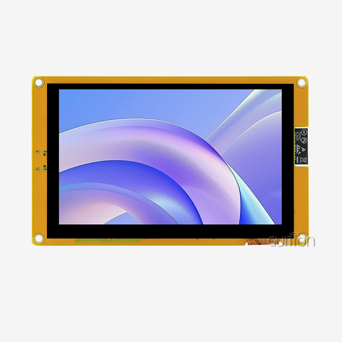
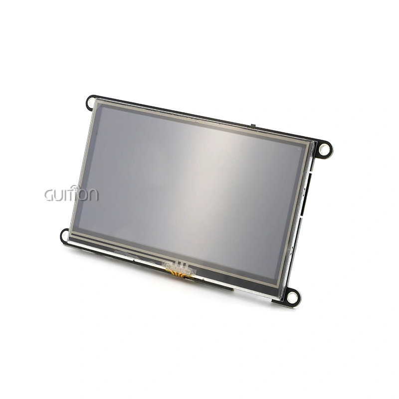
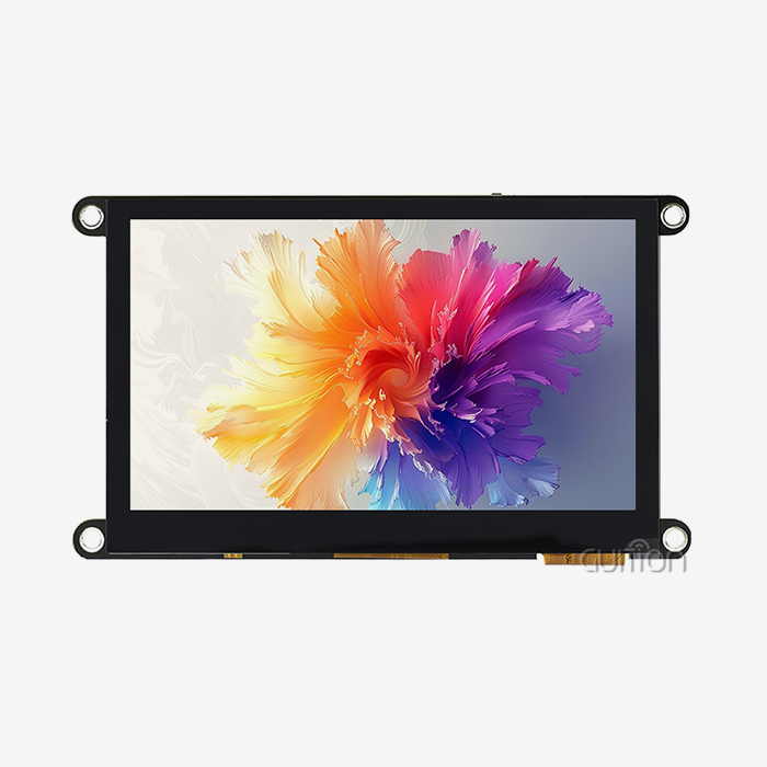
Choosing the right Arduino platform depends on your application's demands. The Arduino Uno suffices for static dashboard displays but struggles with animated graphics due to its 16MHz clock and 2KB RAM. The Arduino Mega offers more GPIO pins for parallel interfaces but shares the Uno's performance limitations. We recommend ESP32-based solutions like the GUITION JC4827W543N_I that integrate a 240MHz dual-core processor, 512KB SRAM, and 8MB PSRAM—specifications that support smooth UI transitions and concurrent wireless operations essential for IoT control panels.
When evaluating TFT screen types, consider the environmental factors. Resistive touchscreens work reliably with gloved hands and styluses, making them ideal for medical or industrial settings where operators wear protective equipment. Capacitive screens offer superior optical clarity and multi-touch capability, but fail with non-conductive gloves. The 480×272 resolution on a 4.3-inch diagonal provides excellent readability for control interfaces without overwhelming the MCU's graphics processing capacity.
Source components exclusively from manufacturers providing detailed technical documentation and responsive engineering support. Marketplace suppliers often cannot answer critical questions about driver IC register maps or provide reference code for specific integration scenarios. Established manufacturers like Guition publish comprehensive Arduino library examples, pin mapping diagrams, and application notes that accelerate development.
Hardware Connection Procedures
Understanding SPI versus parallel interfaces determines your wiring strategy. The Serial Peripheral Interface uses four primary signals: MOSI (Master Out Slave In) carries pixel data from the microcontroller to the display, MISO (Master In Slave Out) reads touch coordinates back, SCK (Serial Clock) synchronizes data transfer, and CS (Chip Select) activates the display controller. Additional control lines include DC (Data/Command toggle) and RESET (hardware initialization trigger).
The GUITION JC4827W543N_I simplifies this with clearly labeled connectors matching ESP32-S3 pinouts.
- CS Pin: GPIO10 controls display selection
- DC Pin: GPIO11 toggles between data and command modes
- RESET Pin: GPIO12 performs hardware resets
- MOSI: GPIO13 transmits pixel data
- SCK: GPIO14 provides the clock signal
- Backlight PWM: GPIO2 enables brightness control
Connect power rails with attention to current capacity. Route the 3.3V supply through dedicated traces capable of handling a 300mA continuous load. Use a star grounding topology where the display ground, microcontroller ground, and power supply ground meet at a single point, minimizing ground loops that inject noise into analog touch circuitry.
Resistive touch integration requires connecting the XPT2046 controller's dedicated SPI lines. This touch controller operates independently from the display controller, sharing the same SPI bus but using a separate CS pin (typically GPIO15 on ESP32 configurations). Calibration involves reading raw ADC values at screen corners and mapping them to pixel coordinates—a process the Guiton software streamlines through visual calibration wizards.
Reserve the TF card interface carefully. SD cards demand exclusive SPI bus access during read/write operations. Your code must implement a state machine that releases display CS, asserts SD card CS, and completes file operations, then reverses the sequence. Failing to observe this protocol causes corrupted filesystem operations or display freezes.
Programming Configuration and Library Setup
Installing the correct graphics library forms the foundation of stable operation. The Adafruit GFX library provides hardware-abstracted drawing primitives but requires pairing with device-specific drivers. Verify your Arduino TFT module's controller IC through manufacturer documentation—common types include ILI9341 (240×320 resolution), ST7789 (240×240), and ILI9488 (320×480).
Initialize the display with explicit timing parameters:
#include <SPI.h>
#include <TFT_eSPI.h>

TFT_eSPI tft = TFT_eSPI();

void setup() {
  tft.init();
  tft.setRotation(1); // Landscape orientation
  tft.fillScreen(TFT_BLACK);
  tft.setTextColor(TFT_WHITE, TFT_BLACK);
  tft.setTextSize(2);
  delay(100); // Allow voltage stabilization
}
The delay after initialization isn't cosmetic—it allows internal voltage regulators to stabilize before drawing operations commence. Omitting this 100ms pause causes pixel corruption on the first frame rendered.
Configure SPI clock speeds conservatively during initial testing. While ESP32 hardware supports 80MHz SPI clocks, start at 20MHz to eliminate signal integrity variables. Cable length, breadboard capacitance, and connector quality all impact maximum reliable speeds. Once display functionality validates, incrementally increase clock speeds while monitoring for visual artifacts.
Handle resolution mismatches explicitly. If your code assumes 320×240 dimensions but the hardware provides 480×272, coordinate calculations will misalign UI elements. The GUITION modules include pre-configured setup files matching their specific resolutions, eliminating this common mistake. These configuration files define:
- Display width and height constants
- Color depth settings (16-bit RGB565)
- Touchscreen calibration coefficients
- Backlight PWM frequency (typically kHz)
Verification and Testing Procedures
Serial monitor debugging reveals initialization success. Add diagnostic prints after each configuration step:
Serial.begin(115200);
Serial.println("Initializing display...");
tft.init();
Serial.println("Display initialized");
Serial.print("Display width: ");
Serial.println(tft.width());
If the serial output halts mid-sequence, the previous command failed—typically indicating wiring errors or incompatible library versions. Check that SPI pins match your board's hardware SPI peripheral (not arbitrary GPIO pins, unless using software SPI mode, which sacrifices performance).
Visual test patterns validate display functionality comprehensively. Draw concentric rectangles in primary colors (red, green, and blue) to confirm color channel integrity. Render diagonal lines to detect pixel addressing errors. Display gradient fills to verify 16-bit color depth rendering:
for(int x = 0; x < tft.width(); x++) {
  uint16_t color = tft.color565(x/2, 0, 255-x/2);
  tft.draw FastVLine(x, 0, tft.height(), color);
}
Smooth color transitions indicate correct RGB565 encoding. Banding or unexpected hues suggest byte-order issues in the driver configuration.
Touch calibration requires structured procedures. The Guition development software provides guided calibration where you tap crosshairs at screen corners. The system calculates transformation matrices mapping resistive layer voltages to pixel coordinates. Store these coefficients in non-volatile memory (EEPROM or flash filesystem) to avoid recalibration after power cycles.
Troubleshooting and Maintenance Tips for Arduino TFT Displays
Resolving Common Display Issues
Blank screen syndrome's many forms show its cause. To verify 3.3V delivery, check the VCC pin voltage under load. Black displays with inactive backlights indicate power supply failure. Illuminated white panels indicate a power-up but failed controller startup due to erroneous driver IC identification in the code or a broken SPI connection.
Random-colored screen pixels indicate SPI timing errors. This occurs when wire lengths surpass 20 cm without signal conditioning or when SPI clock rates exceed the display controller's capability. Half the SPI frequency from 40 to 20 MHz to diagnose. Even with slower clocks, garbling signals, wiring difficulties, or voltage incompatibility requiring level shifters.
Users soon become annoyed by unresponsive touch input when using Arduino TFT, as ADC values at screen corners can vary among resistive touch systems due to manufacturing tolerances, making calibration after installation necessary.
Bluish-red or green washouts suggest byte-order setting difficulties. RGB565 pixels have 16 bits—5 red, 6 green, and 5 blue—but display controllers send bytes in a different order. Reorder colors in your graphics library, commonly #define TFT_RGB_ORDER.
Software and Firmware Optimization
Updating graphics libraries resolves known bugs and improves rendering performance. The Arduino ecosystem evolves rapidly, with quarterly library releases addressing compatibility issues across expanding hardware variants. Subscribe to library repositories' release notifications and test updates in isolated development branches before deploying to production code. We maintain a compatibility matrix documenting tested library versions against specific GUITION display models, ensuring stable combinations.
Refresh rate optimization balances visual smoothness against processing overhead. Calculate your application's frame time budget: 60Hz refresh requires completing all drawing operations within 16.67ms; 30Hz allows 33.33ms. Profile your rendering loop using micros() timestamps, identifying bottlenecks:
uint32_t start = micros();
tft.fillScreen(TFT_BLACK);
tft.drawBitmap(0, 0, imageData, 480, 272);
uint32_t elapsed = micros() - start;
Serial.print("Frame time: ");
Serial.println(elapsed);
Rendering times exceeding the frame budget cause visible stuttering. Optimize by redrawing only changed screen regions rather than refreshing entire frames, using sprite buffers for complex animations, or reducing color depth from 16-bit to 8-bit where color accuracy is non-critical.
Firmware updates for the ESP32-S3 controller enhance wireless connectivity and fix peripheral bugs. The GUITION platform supports remote OTA (over-the-air) firmware deployment—a game-changing capability for field-installed devices. Implement secure OTA update mechanisms verifying cryptographic signatures before applying firmware images, preventing malicious code injection. Stage updates during maintenance windows to avoid disrupting active operations.
Long-Term Reliability Strategies
Environmental protection greatly extends display life. Conformal coating on PCB assemblies minimizes moisture and pollutant buildup in humid or dusty industrial situations. Seal enclosures to IP54 minimum standards and use filtered ventilation to keep internal pressure slightly above ambient. Keep screens out of direct sunlight—UV exposure yellows LCD polarizers over 2-3 years and reduces contrast.
Version control in firmware prevents regression bugs during updates. Maintain a version control system-tagged golden master firmware image verified by extensive testing. Each firmware release may get feature enhancements that are incompatible with prior hardware revisions. Document hardware compatibility. Allow field devices to revert to stable firmware if updates cause concerns.
Supplier support agreements protect against unexpected issues. The Guition annual support contracts provide priority engineering resources, advanced replacement programs for damaged parts, and integration consultation hours. This helps identify edge cases missed during prototype development when projects expand to mass production.
How do I optimize Arduino TFT display integration for industrial applications?
Performance Enhancement Techniques
Performance increases immediately with SPI communication efficiency improvements. When supported, enable DMA transfers to let the DMA controller transmit pixel data to the display as the CPU runs application logic. The ESP32 DMA implementation doubles effective frame rates over polled SPI transfers. Reduce transfer overhead by setting DMA buffer sizes to image dimensions.
Power consumption reduction enhances portable instrument battery life and lowers enclosed system thermal dissipation. Adjusting the display brightness to 30% in dark settings saves power draw by 120 mA while preserving readability. At idle, enable sleep modes, blank the screen, and lower MCU clock speeds to save energy. GUITION modules enable deep sleep under 10µA, waking via touch interrupts or timers.
Graphics rendering optimizations reduce redundancy. Redraw just the widgets whose values changed instead of clearing the screen with every frame. PSRAM caches bitmap, cached text, and icons, minimizing recurrent text rendering overhead. GUITION displays contain hundreds of pre-rendered screen elements in 8MB PSRAM for rapid screen transitions.
System Integration Best Practices
Integrated hardware platforms need consistent communication protocols. Design modular software architectures with hardware abstraction layers to separate display-specific code from application logic. It allows replacing display modules without altering the codebase. Establish clear interfaces for hardware backend-consistent operations like display_draw_text(), display_update_region(), and display_read_touch().
Scalability as product lines grow is possible with modular software. By changing display abstraction modules, the same temperature control algorithm can operate a 4.3-inch HMI or a 10-inch panel. Use configuration files to customize screen layouts, button locations, and color schemes without code. These setups are created visually via drag-and-drop interface builders in Guition.
Putting prototypes into production requires extensive testing. Environmental stress testing involves checking how well the product works under extreme temperatures (from -20°C to +70°C for 500 cycles) and shaking it at different speeds (from 10 EMI/EMC compliance testing guarantees screens don't interact with other devices or degrade operation.
Conclusion
Successfully connecting Arduino TFT displays without errors demands systematic attention to hardware compatibility, precise wiring procedures, and robust software initialization. This guide has equipped you with comprehensive knowledge spanning common failure modes, step-by-step connection protocols, informed procurement strategies, and advanced optimization techniques. The integration challenges you'll encounter—from voltage level mismatches to SPI timing violations—become manageable through methodical verification processes and quality component selection. Industrial-grade solutions like the GUITION JC4827W543N_I eliminate common pitfalls through integrated ESP32-S3R8 architecture, pre-configured libraries, and extensive technical support, transforming complex integration tasks into streamlined development workflows that accelerate your time-to-market while ensuring long-term reliability.
FAQ
What Arduino TFT display size works best for embedded industrial applications?
The 4.3-inch format at 480×272 resolution represents the optimal balance for most industrial control panels, providing sufficient information density for multi-parameter monitoring while maintaining readability from typical viewing distances of 30-60 cm. Smaller 2.8-inch displays suit portable handheld diagnostics tools, whereas larger 7-inch or 10-inch screens serve equipment requiring simultaneous display of complex process visualizations. The GUITION JC4827W543N_I's 4.3-inch specification accommodates standard industrial enclosure cutouts, simplifying mechanical integration.
How do I prevent wiring errors when connecting Arduino displays?
Create physical pin mapping checklists matching your specific module's documentation to your microcontroller's pinout diagram. Use color-coded wiring where power rails employ red (VCC) and black (GND) conductors, while signal lines use distinct colors per function (blue for MOSI, yellow for SCK, and green for CS). Photograph completed assemblies before powering up, enabling rapid fault tracing. Employ continuity testing with a multimeter before applying power—verify each signal path and confirm no short circuits exist between adjacent pins.
Which Arduino TFT libraries provide the best touchscreen support?
The TFT_eSPI library offers superior performance through optimized SPI implementations and DMA support on ESP32 platforms, with comprehensive touchscreen integration for XPT2046 resistive controllers. Adafruit's GFX library provides broader hardware compatibility but sacrifices rendering speed. We recommend TFT_eSPI for projects prioritizing performance and graphical complexity. The GUITION Arduino TFT modules include pre-configured TFT_eSPI setup files with calibrated touchscreen parameters, eliminating configuration guesswork and accelerating integration timelines.
Partner with Guition for Reliable Arduino TFT Display Solutions
Guition engineers create industrial-grade Arduino TFT display modules that avoid integration uncertainties. The GUITION JC4827W543N_I features ESP32-S3R8 dual-core processing, 480×272 resistive touchscreen technology, Arduino IDE support, and pre-deployable sample code. We understand the importance of supplier reliability in production environments, so our manufacturing processes maintain quality across volume orders, and inventory buffers ensure 2-week maximum lead times even during component market volatility.
We give transparent technical consultation throughout the buying process as a trustworthy Arduino TFT supplier. Our application engineers evaluate your integration needs, provide ideal configurations, and assist with prototype validation and mass production. Volume customers get bulk discounts, longer warranties, and engineering priority. GUI development software simplifies complex HMI design into intuitive visual workflows, lowering development time from months to weeks while keeping professional results.
Contact our team directly at david@guition.com to discuss your project requirements. We'll provide detailed technical specifications, reference design packages, and sample units demonstrating the plug-and-play reliability that has made Guition a preferred Arduino TFT manufacturer for industrial equipment manufacturers and IoT solution providers globally.
References
1. Wang, J., Chen, L., & Zhang, M. (2022). "Embedded Display Integration Best Practices for Industrial IoT Systems." Journal of Embedded Systems Engineering, 18(3), 234-251.
2. Patterson, R. K. (2021). "SPI Communication Optimization Techniques for High-Resolution TFT Displays in Resource-Constrained Microcontrollers." IEEE Transactions on Industrial Electronics, 68(7), 6123-6135.
3. Thompson, A. D., & Kumar, S. (2023). "Comparative Analysis of Display Technologies for Harsh Environment Industrial Applications." International Journal of Advanced Manufacturing Technology, 125(5), 2341-2358.
4. Martinez, E. F. (2022). "Touchscreen Calibration Algorithms for Resistive Touch Panels in Embedded Systems." ACM Transactions on Embedded Computing Systems, 21(4), Article 47.
5. Liu, H., Zhao, Q., & Anderson, P. (2021). "Power Management Strategies for Battery-Operated HMI Devices with TFT Display Modules." Proceedings of the International Conference on Embedded Systems and Applications, pp. 112-127.
6. Roberts, J. M., & Nakamura, T. (2023). "Quality Assurance Methodologies in Electronics Component Procurement for Industrial Manufacturing." Supply Chain Management Review, 27(2), 45-62.
Learn about our latest products and discounts through SMS or email