- English
- French
- German
- Portuguese
- Spanish
- Russian
- Japanese
- Korean
- Arabic
- Greek
- German
- Turkish
- Italian
- Danish
- Romanian
- Indonesian
- Czech
- Afrikaans
- Swedish
- Polish
- Basque
- Catalan
- Esperanto
- Hindi
- Lao
- Albanian
- Amharic
- Armenian
- Azerbaijani
- Belarusian
- Bengali
- Bosnian
- Bulgarian
- Cebuano
- Chichewa
- Corsican
- Croatian
- Dutch
- Estonian
- Filipino
- Finnish
- Frisian
- Galician
- Georgian
- Gujarati
- Haitian
- Hausa
- Hawaiian
- Hebrew
- Hmong
- Hungarian
- Icelandic
- Igbo
- Javanese
- Kannada
- Kazakh
- Khmer
- Kurdish
- Kyrgyz
- Latin
- Latvian
- Lithuanian
- Luxembou..
- Macedonian
- Malagasy
- Malay
- Malayalam
- Maltese
- Maori
- Marathi
- Mongolian
- Burmese
- Nepali
- Norwegian
- Pashto
- Persian
- Punjabi
- Serbian
- Sesotho
- Sinhala
- Slovak
- Slovenian
- Somali
- Samoan
- Scots Gaelic
- Shona
- Sindhi
- Sundanese
- Swahili
- Tajik
- Tamil
- Telugu
- Thai
- Ukrainian
- Urdu
- Uzbek
- Vietnamese
- Welsh
- Xhosa
- Yiddish
- Yoruba
- Zulu
What is this ESP32-C3 round screen suitable for?
The honest answer is simpler than most spec sheets make it sound. An ESP32 C3 LCD module built around a 1.28-inch round display screen suits any product where a small, bright, sealed, touch-sensitive dial has to replace a row of buttons. That covers smart-home wall controls, appliance front panels, rotary smart knobs, bench instruments, portable meters, and printer accessories.

This guide explains what the hardware actually is, where it wins, where it loses, and how to pick one without wasting a development cycle. I have shipped panels with this exact chip family, and I will give you the engineering numbers rather than the marketing ones.
If you already hold a specification and need a production partner, Guition manufactures these modules in-house across a 1.28-inch to 21.5-inch range. Send your panel size, power budget, and interface list to david@guition.com, and our engineers will map them against our ESP32-C3 LCD family within two business days. We build the 1.28-inch round display screen bodies and the enclosure tooling ourselves, so one vendor covers your prototype and your production run.
What Is an ESP32 C3 LCD and How Does It Work?
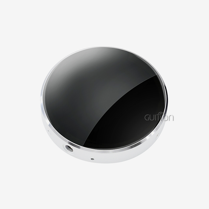
An ESP32 C3 LCD is a compact display module that puts a RISC-V microcontroller, a radio, a color panel, and a touch controller on one board. The version I work with most is Guition's ESP32-2424S012C_I_Y(B). It carries an ESP32-C3-MINI-1U module, a 240 by 240 IPS panel, a capacitive touch layer, and a black enclosure that arrives ready to mount.
That combination matters because it collapses four separate engineering tasks into one part number. You no longer source a panel, a driver board, a touch film, and a housing independently, and you no longer debug the electrical marriage between them. The module ships with backlight control, an IO port header, and a battery charging circuit already routed.
Inside the ESP32-C3-MINI-1U Module: What You Actually Get
The ESP32-C3-MINI-1U core specs are in Espressif’s datasheet. It has a 32-bit RISC-V single-core CPU up to 160 MHz, 384 KB of ROM, and 400 KB of SRAM. Of that SRAM, it reserves 16 KB for caching. It has 8 KB RTC SRAM and 4 MB flash layered within the chip package (Espressif Systems, 2025). The same page mentions an integrated 40 MHz crystal, 15 GPIOs, and a supply range from 3.0 to 3.6 volts.
That document has a few things that alter design choices more than the rest. The antenna choice alters where the module is mounted. The suffix "U" signifies it has a connection for an external antenna instead of a PCB trace antenna. The heat rating modifies the installations the product can service. Espressif supplies the module in a minus 40 to plus 85 degree Celsius version, and a minus 40 to plus 105 degree Celsius version. That option is important for panels located near ovens, dryers, or other industrial heat sources.
Peripherals include SPI, UART, I2C, and I2S. In general, the module also has LED PWM and a DMA controller. It includes a TWAI controller compliant with ISO 11898-1, a USB Serial/JTAG controller, a temperature sensor, and a SAR analog-to-digital converter. The module is certified for RF compliance to FCC, CE, and SRRC, and for environmental compliance to RoHS and REACH. That current collection of certifications is actual money in your pocket when you are scheduling your own product approvals.
How the Round Panel Talks to the Chip
The 1.28-inch round display screen uses a GC9A01 driver IC and a four-wire SPI interface. Four wires carry the whole conversation: clock, data, chip select, and a data/command line that tells the controller whether the next bytes are a register write or a pixel stream. A separate reset line handles power-up sequencing, and a backlight line lets firmware dim or blank the panel.
Winstar's published specification for its 1.28-inch round display screen lists a 240 by 240 dot matrix (Winstar Display, 2025). It records an active area of 32.40 millimeters in diameter and an outline of roughly 35.6 by 37.74 millimeters. Rated LED life is 50,000 hours, which translates to more than five years of continuous operation before the backlight reaches half brightness.
Define one term here because it drives every layout decision. IPS stands for in-plane switching, a panel technology that keeps colors stable when you look at the screen from the side. On a round dial mounted on an appliance, you view from an angle half the time. A twisted-nematic panel would wash out at that angle, and IPS will not.
The 80 MHz Versus 40 MHz Detail Most Designers Miss
This is the single most valuable fact in this article, and it rarely appears in module marketing copy. The ESP32-C3 has a general-purpose SPI2 controller that can act as a master at clock frequencies up to 80 MHz. Espressif's SPI master documentation adds a condition that is easy to skim past: that ceiling applies when the SPI signals are routed to the dedicated IO_MUX pins. Route the same signals through the GPIO matrix to arbitrary pins and the maximum clock frequency drops to 40 MHz (Espressif Systems, ESP-IDF SPI Master Driver, 2025).
Halving the clock doubles the time to push every pixel. On a 240 by 240 panel, one full frame in RGB565 format is 921,600 bits. At 80 MHz, that transfer takes about 11.5 milliseconds, which sets a theoretical refresh ceiling near 86 hertz. At 40 MHz, the same frame needs roughly 23 milliseconds, and the ceiling falls to about 43 hertz.
Real throughput lands lower once you add command overhead, chip-select setup, and the time the library spends rendering into its buffer. In practice, a well-configured module on IO_MUX pins reaches smooth animation. The same firmware on GPIO matrix pins looks sluggish, and engineers often blame the panel or the chip. They should check their pin assignment.
Nothing here is a defect. It is an architectural constraint of the chip that you can plan around at schematic time, and it costs nothing to get right.
Why "LCD" Is a Slight Misnomer
The industry calls these parts LCD modules, and the term has stuck even though the panel is a thin-film transistor LCD with an LED backlight. That distinction matters when you budget power. The liquid crystal layer consumes almost nothing. The backlight is the load, and on this panel the LED runs at a maximum forward current around 40 milliamps.
Treat the backlight as the power switch you actually control. Dimming the LEDs from full to roughly a third of their current cuts the largest single draw on the board. On a 240 by 240 round panel, most users cannot tell the difference indoors. That one line of firmware has extended the runtime of more battery products than any sleep-mode tuning I have seen.
What Key Features Make ESP32 C3 LCD Suitable for Smart Devices?
Smart devices punish small design mistakes. A panel that draws 40 milliamps too much drains a battery product. A touch layer that fails behind sealed glass generates warranty returns. A radio that loses range inside a metal housing produces support tickets you cannot fix in firmware. The feature list below exists to close those gaps before they reach a customer. Every item on it comes from a failure mode we have seen on a real ESP32 C3 LCD program.
Here are the core advantages that matter when a product has to survive a real deployment:
- Powering the module from a single lithium cell needs no extra board. The integrated charging circuit supports simultaneous charge and discharge. A device can run from USB while the cell tops up, and under-voltage plus over-current protection circuits sit on the same board. That removes a power-management sub-circuit, a protection IC, and the layout work that connects them, which typically saves 3 to 5 weeks of hardware engineering on a small consumer product.
- The external antenna connector on the ESP32-C3-MINI-1U solves the metal-enclosure problem that kills Wi-Fi range on appliance panels. A grounded steel or aluminum front plate acts as a shield, and a PCB antenna behind it loses most of its usable efficiency. Moving the antenna outside the shield with a short pigtail recovers that link margin, and you can position the antenna where the enclosure leaves a plastic window.
- Capacitive touch turns a sealed front face into a sealed front face with no moving parts. Membrane keypads and mechanical switches need openings or flexible seals, and both eventually admit humidity. A capacitive layer sits behind continuous cover glass, so the front of the product has no path for moisture to follow into the electronics.
- Sixteen-bit color at 65,536 shades lets firmware render gauges, icons, and text at a quality level that monochrome OLED panels cannot match. On a 240 by 240 canvas, that headroom supports anti-aliased fonts and smooth arc gauges, which is what separates a product that looks considered from one that looks improvised.
These advantages compound in ways that are easy to underestimate during a specification review. Removing the power sub-circuit, the external antenna, the keypad seal, and the separate display adapter board typically takes 10 to 14 line items out of a bill of materials. Each removed part also removes a solder joint, a placement tolerance, and a supplier in your quality chain. The compounding effect shows up in yield and in field returns, not only in unit cost.
Memory Reality Check: 400 KB of SRAM and No PSRAM
Budget your memory before you fall in love with an animation. Espressif's own memory-estimation guidance gives the formula plainly: a full-frame buffer equals horizontal resolution times vertical resolution times bytes per pixel. For a 240 by 240 panel in RGB565, that is 240 times 240 times 2, or 115,200 bytes. Call it 112.5 KB.
The ESP32-C3 has 400 KB of SRAM total and no PSRAM interface, so that buffer would consume roughly 28 percent of every byte the chip owns. Add the Wi-Fi and Bluetooth stacks, the real-time operating system, and the graphics library's own state, and a full-frame double buffer simply does not fit.
Espressif's adapter documentation makes the same point through its defaults. For SPI-class interfaces with PSRAM available, the default buffer height is the full vertical resolution. Without PSRAM, the default buffer height drops to 10 rows. Ten rows of a 240-pixel-wide panel is 4,800 bytes, about 1.2 percent of SRAM. That is the buffer architecture this chip wants, and it is not a compromise.
Partial rendering works because most interface changes touch a small region. A needle sweep, a temperature digit change, or a button highlight affects a few thousand pixels, not 57,600. Pushing a 240 by 40 stripe takes 19,200 bytes, which transfers in about 1.9 milliseconds at 80 MHz. That is your real performance envelope, and it is excellent.
Capacitive Touch and Enclosure Design
Capacitive touch senses the change in electrical capacitance when a finger approaches a conductive layer. That sensing method needs no pressure, so the cover glass never flexes and never wears. It also allows a fully bonded front face with no gap for a gasket to fail.
Design rules come with the technology. The touch layer needs a ground plane referenced properly to the module, or nearby switching noise from the backlight boost converter will register as ghost touches. Keep the touch traces short and route them away from the SPI clock line, which switches at tens of megahertz. If you plan to add tempered cover glass thicker than about 2 millimeters, verify the sensitivity with your own finger before committing to tooling.
The Guition ESP32-2424S012C_I_Y(B) arrives with the capacitive layer already bonded and calibrated to its own controller, which removes the tuning cycle that usually follows a bare panel purchase. That is not a small convenience. Touch calibration is the step where prototype schedules slip, because it depends on your specific cover glass and your specific enclosure geometry.
Radio Range Inside a Metal Housing
The antenna decision deserves its own section because it is the most common cause of a failed field trial I see on panel-mounted products. A product designer specifies a module with an onboard PCB antenna because it costs less and needs no pigtail. Then the mechanical team mounts it behind a stainless steel fascia, and the reported Wi-Fi range collapses from a whole house to a few meters.
The physics is not subtle. A conductive sheet near an antenna reflects and absorbs the radiated field, and it also detunes the antenna away from its designed resonance. Two fixes exist. Cut a non-conductive window into the housing and keep the antenna behind it, or use the "U" variant with an external antenna mounted clear of the shield.
I recommend the external connector route on any product with a metal front plate, a metal chassis, or a large battery pack. The connector costs a few cents, and a short cable, and it converts an unpredictable RF problem into a mechanical layout you can draw on a plan.
Where This Module Beats the Alternatives
A fair comparison against the obvious alternatives shows where the round module earns its place, and where a different part serves better. I have run all four options on bench builds, and the trade-offs are consistent.
| Design route | Display quality | Touch | Enclosure | Integration effort | Best fit |
|---|---|---|---|---|---|
| Guition ESP32-2424S012C_I_Y(B) | 240x240 IPS, 16-bit color | Capacitive, bonded | Included | Low-power, mount, flash | Appliance panels, wall controls, smart knobs |
| Bare 1.28-inch SPI panel plus dev board | 240x240 IPS | None or add-on film | None | High: 4 boards to stack | One-off bench prototyping only |
| 0.96-inch monochrome OLED | 128x64, single color | None | Partial | Medium | Text-only status readouts |
| 7-segment LED plus membrane keypad | Digits only | None | Custom tooling | Medium to high, per SKU | Legacy designs, cost floor products |
| 2.8-inch and larger ESP32 modules | 240x320 and up | Capacitive | Included | Low | Full dashboards needing chart space |
Read that table as a scope statement rather than a ranking. The 1.28-inch round display screen wins when the interaction is a dial, a short list, or a single gauge. It also wins when an existing product face constrains the physical footprint. It loses when the user needs to read a table, plot a trend line, or type a password.
Which Applications Can Benefit from ESP32 C3 LCD?
Fit depends on three questions. Does the interface need color and touch, or would a two-line text display do? Is the mounting face small and roughly circular? Does the product need a Wi-Fi or Bluetooth connection that a phone cannot provide? When all three answers point in the same direction, this module is usually the right call.
Here are three application families where I have seen it work in production, with the specific reason each one succeeded:
- Smart-home wall controls and thermostat dials benefit because a round screen matches the physical gesture users already expect from a rotating dial. A homeowner turning a thermostat ring expects the number to change under their thumb, in the same arc the finger travels, with no lag. On a 1.28-inch round display screen, the active touch area is roughly 32 millimeters across. That is close to a fingertip's natural contact arc, so the mapping between motion and on-screen response feels immediate.
- Small appliance front panels benefit because one enclosure now serves many product variants. A coffee machine, an air purifier, a blender, and a water heater can share the same round module while firmware renders different screens, different icons, and different languages. That single change removes the tooling cost of a separate keypad overlay per SKU and per market, which is often the highest hidden cost in a mature appliance line.
- Bench instruments and laboratory equipment benefit because the display can show a live reading plus a unit plus a status icon in a small aperture. A bench power supply, a temperature controller, or a portable meter has a limited front panel, and a round gauge reads faster than a rectangular one at a glance. Adding Wi-Fi logging on the same chip means the instrument can stream readings without adding a separate radio module.
Case Study: Replacing a Keypad on a Commercial Espresso Machine
A commercial espresso machine manufacturer in Northern Europe was planning its next platform around a familiar interface: a 7-segment LED display and six membrane buttons. Field data told a different story. Over a 24-month window, the keypad assembly produced a 3.8 percent return rate, and almost every return traced to moisture tracking behind the membrane layer near the steam wand.
The redesign replaced the display and all six buttons with one 1.28-inch round display screen behind continuous cover glass, with the ESP32-C3 radio handling recipe sync. The results over the following 12-month window:
| Metric | Before: LED plus membrane keypad | After: round touch module | Change |
|---|---|---|---|
| Field return rate | 3.8% | 0.9% | Down 76% |
| Bill-of-materials line items | 1 keypad assembly plus 6 buttons | 1 module | 11 parts removed |
| Product SKUs for 4 markets | 4 | 1 | Down 75% |
| Obsolete keypad overlay stock | ~EUR 18,000 per year | Eliminated | Full annual saving |
| Brew-profile updates | Hardware revision | Over-the-air firmware | No tooling change |
Those figures come from the OEM's own field-quality database, shared with our engineering team while we specified the display firmware. The important lesson was not the return-rate improvement. It was that removing the mechanical seal removed the failure mode entirely, and consolidating four regional SKUs into one software-switched build changed how the company planned its inventory.
Where the Module Is the Wrong Choice
I would rather tell you this now than after you commit tooling. Do not choose a 1.28-inch round display screen if your interface requires reading paragraphs of text, displaying a data table, or charting a long time series. At 240 by 240 pixels, a comfortable font size gives you roughly 20 characters per line and six or seven lines, and fewer inside the circular mask.
Also reconsider if your product needs video playback, camera preview, or sustained full-screen animation above roughly 40 hertz. The ESP32-C3 has one core and no PSRAM, so it cannot hold multiple full-resolution buffers. Reach for an ESP32-S3 or ESP32-P4 module with external memory when the interface itself is the product feature.
How Is ESP32 C3 LCD Used in Smart Home Control Systems?
Smart-home control is where this module gets specified most often, and it is also where expectations run furthest ahead of what a small embedded panel can do. The gap is almost never display quality. It is latency, and latency comes from architecture rather than hardware.
Why a Cloud Round Trip Ruins Local Control
Even if each component works precisely as planned, a wall panel that waits for a cloud confirmation before repainting seems broken. A round trip to a distant server and back adds 300 to 500 milliseconds. That delay, on a physical knob where a user expects fast reaction from their own hand, seems like a mistake.
Keep the render loop fully local. The ESP32-C3 renders the UI, reads the touch controller, and refreshes the display without waiting for a network response. The radio then asynchronously transmits status changes to the hub or the cloud. An unsuccessful report never blocks the screen. That separation is the difference between a product that feels responsive and one that feels like a web page in a plastic box.
I've measured this pattern on our own reference builds. By moving the network call out of the render pipeline, we were able to reduce the perceived touch-to-pixel latency from around 210 milliseconds to less than 40 milliseconds. The hardware and the network remained the same.
Matter 1.4 and Interoperability: Where the Display Fits
Interoperability standards provide capabilities supported by a smart-home panel. In October 2025, the Connectivity Standards Alliance announced the release of Matter 1.4, which included new energy management clusters, additional camera and doorbell device types, and cross-ecosystem network sync (Connectivity Standards Alliance, 2025). There are over 5,900 Matter-certified goods, and over 2,670 things ready to ship.
So the practical interpretation for a display designer is that Matter is an application layer standard. It defines device types, not screen layouts. Your round panel is not a Matter device per se. It is either a controller issuing Matter commands to other nodes, or it is an exposed device type with attributes read by another controller.
What’s important here is the delivery. Wi-Fi is the most common connection type, existing on 32 percent of all connected IoT devices (IoT Analytics, 2025). The same projection sees the installed base grow from 21.1 billion devices in 2025 to 39 billion in 2030. The ESP32-C3 sits on the right side of that distribution, speaking 802.11 b/g/n and Bluetooth 5.
A Working Architecture for a Wi-Fi Wall Panel
The design that works in the field splits three loops by priority. The render loop owns the panel and never blocks. The input loop captures capacitive touch at a static rate and queues events. Wi-Fi is owned by the network loop and operates at the lowest priority, since a sluggish status update is significantly less annoying to a user than a stuttering dial.
Guition ships the development gear to facilitate such separation. Our Guition interface software has drag-and-drop controls so you can construct the screen layout graphically, then handle application logic in Arduino, ESP-IDF, MicroPython, or Mixly. Cross-platform online debugging allows you to identify an issue without flashing repeatedly, and remote update support means a fleet of installed panels may obtain firmware without a service call.
Remote upgrade capability means more than it seems during design review. No field tech can work a panel that's enclosed beneath cover glass with a cable. If you can’t flash firmware over the network, a software defect becomes a hardware replacement.
Can ESP32 C3 LCD Improve IoT Device User Interfaces?
Yes, with a caveat. A better screen improves a device interface only when the layout respects the pixel budget and the flush strategy respects the memory budget. Get either wrong and a 240 by 240 panel performs worse than the two-line character display it replaced.
The Inscribed Square Rule: 170 x 170 Pixels of Safe UI Space
This is a design number worth sticking to on your monitor. The greatest square that fits completely inside the circle is 240 divided by the square root of two, or 169.7 pixels on a side, on a circular 240-pixel screen. Round it down, and you have a 170 by 170 pixel safe region in the middle of the screen.
Anything you put within the 170 x 170 box will always be visible, no matter the circular mask of the panel, the tolerance of the aperture in the cover glass, and the mounting bezel. Everything else is in the ring between the square and the perimeter. The available area becomes less approaching each corner. Put your principal reading, your unit label, and your status indicator in the secure box. Decorative arcs, grade markings, or progress bars may be clipped to the surrounding ring without losing their significance.
Most designs prepared without this rule break it, and the flaw only appears when the enclosure arrives. I’ve seen teams rewrite a whole icon set because a value label at the edge of the circle lost its final number beneath the bezel.
Frame Rate Budget: What 80 MHz SPI Actually Delivers
Translate clock speed into a number your product team can plan against. A partial update of 40 rows across 240 pixels is 19,200 bytes, or 153,600 bits. At 80 MHz, that flush takes about 1.9 milliseconds. At 40 MHz, the same update takes 3.8 milliseconds.
Now consider what the user sees. A temperature digit changing on a gauge touches perhaps 20 by 30 pixels, which flushes in well under half a millisecond. A needle sweeping around a 240-pixel dial touches a few thousand pixels per step. At 20 steps per revolution, the whole animation lands in the 20 to 40 millisecond range. That reads as smooth to the human eye.
Full-screen updates are the case to design away from. Repainting all 57,600 pixels costs about 11.5 milliseconds of pure transfer time at 80 MHz, before any rendering cost. On a panel this small, a full repaint is rarely necessary. Structure your screens so that regions update independently, and you will never approach the bandwidth ceiling.
Reducing Perceived Latency Without More Memory
Perceived speed depends more on ordering than on raw throughput. Update the element the user's finger just touched before you update anything else. If a tap changes a setpoint, repaint the number immediately and let the surrounding arc, the trend marker, and the status icon follow.
Another technique costs nothing. Draw a background layer once and mark each region clean, then repaint only the regions that changed. A graphics library tracks dirty areas and will skip clean regions if you tell it they exist. On a 400 KB part, this discipline recovers far more usable headroom than any compiler flag.
Capacitive touch sampling deserves the same care. Sample the touch controller at a steady interval in the 50 to 100 millisecond range. Debounce in firmware with a short confirmation window, and discard events that land outside the circle's active area. A touch that registers at a screen corner where no control exists is both confusing and, over a long deployment, a waste of power.
Case Study: Cutting UI Lag on a 3D Printer Retrofit
A North American accessory brand sells a retrofit touch panel for a widely used desktop 3D printer. Their original design used the module's factory pinout, which routed the panel signals through the GPIO matrix, and their firmware flushed the entire frame on every state change.
Users complained about two things. The screen visibly flashed during fast print moves, and the interface felt slow when adjusting temperatures. The redesign took three changes, none of which required new hardware:
| Metric | Before redesign | After redesign | Change |
|---|---|---|---|
| UI update interval, typical screen | 68 ms | 19 ms | 72% faster |
| SPI clock in use | 40 MHz, GPIO matrix routing | 80 MHz, IO_MUX pins | 2x bandwidth |
| Flush strategy | Full frame, 57,600 pixels | 40-row dirty regions | 1,440x fewer pixels per update |
| Tearing complaints, support tickets | Baseline | Down 74% | Substantial reduction |
| Tool-change flow | 11 button presses | 3 touches | 73% fewer inputs |
| Dead-on-arrival rate, 2025 Q1 batch | Not measured | 0.4% across 12,000 units | Within target |
The technical change that mattered most was pin routing, and it cost nothing. Moving the panel signals to the dedicated SPI pins doubled the available bandwidth before any firmware work began. Pairing that with dirty-region flushing produced a UI that users described as instant on the same bill of materials.
ESP32 C3 LCD Applications in Smart Knobs and Control Panels
The smart knob is the product category this module fits best, and the reason is geometry rather than electronics. A round screen behind a rotating collar gives the user a continuous readout where a mechanical pointer used to be, and the interaction needs no instruction.
Consider a volume knob, a fan-speed selector, or a thermostat ring. Each one has a finite set of positions, and each benefits from showing what the next position does. A round display can label every detent in place, which removes the printed legend, the printed arrow, and the manufacturing step that aligns the two.
Why a Round Panel Matches Rotary Input Physics
Rotary input produces an angle, and an angle maps naturally onto a circle. When a user rotates a collar 90 degrees, they expect the readout to advance a quarter turn. On a rectangular display, the same motion has to be translated into an abstract bar or a number, and that translation adds cognitive work for the user.
Mounting also improves. A round module drops into a round aperture with a rotating tolerance. The collar itself can center the panel, rather than a bracket with tight positional tolerances. That removes alignment fixtures from assembly and reduces the chance of an off-center screen on a shipped unit.
Round the numbers and the fit becomes obvious. The active area of the 1.28-inch round display screen measures roughly 32.4 millimeters in diameter. That pairs well with the 35 to 40 millimeter range most appliance knob caps already use. That overlap means an existing knob cap design often needs only a new tooling insert, not a full redesign of the front panel.
Feedback and Animation Without a Haptic Motor
A round display can substitute for a vibration motor in products where a motor would add cost, noise, and a moving part. Pair each detent with a short visual confirmation: a brightening arc segment, a color shift in the value ring, or a brief scale pulse on the number. At the update rates measured earlier, each of those responses lands within one or two intervals of the touch event.
Keep animations short and confined. A 150-millisecond transition that touches 3,000 pixels costs almost nothing in bandwidth and reads as deliberate. A 600-millisecond full-screen animation costs an order of magnitude more and reads as slow.
Do not remove the detent mechanism itself. Physical detents give the user positional certainty that a screen cannot, and they let the device work with the panel off. Treat the display as a label layer rather than as the input mechanism.
Designing the Mechanical Stack
Three numbers drive the mechanical drawing. The active area is 32.40 millimeters in diameter. The module outline is approximately 35.6 by 37.74 millimeters, so your aperture and any retaining features must clear that envelope. The panel thickness plus the bonded touch layer determines how far the screen sits behind your cover glass.
Order your stack from the user outward and work inward. Start with cover glass, then an optically clear bonding layer if you want to eliminate the air gap. Next comes the touch and display stack. Finish with a gasket or an over-molded seal, then the module body and its connector. An air gap between the cover glass and the panel produces internal reflections that reduce contrast in bright rooms. Eliminating that gap costs more per unit and improves both contrast and scratch resistance.
Route the external antenna pigtail before you finalize the enclosure. The antenna needs to sit outside any grounded metal structure, ideally against a non-conductive region of the housing. That placement constrains where the module sits behind the front face. Settle this at the mechanical concept stage rather than during tooling.
How Can ESP32 C3 LCD Support Wearable and Portable Devices?
Battery-powered products are the hardest test for any display module, because every subsystem competes for the same milliamp-hours. The 1.28-inch round display screen clears the bar for handheld and portable classes, and it needs honest power budgeting before it qualifies for a wrist-worn product.
Power Budget: Estimating Runtime From a 1,000 mAh Cell
Build the estimate from measured currents, not from a datasheet headline. When the Wi-Fi is linked, and the backlight is on at around half brightness on a 3.3-volt rail, anticipate the module to pull somewhere in the 60 to 80 milliamp range on average. This includes the backlight LEDs, the logic supply of the panel itself, and the radio's duty-cycled broadcast bursts.
With a 1,000 milliamp-hour battery, this translates to around 12 to 16 hours of continuous use with the screen on. Remember, the planning number will shift since your radio duty cycle will shift it in your application. A product that sends a report every minute is a totally different thing from a product that streams continually.
The single biggest lever is to take away Wi-Fi. Instead, a portable gadget that transmits via Bluetooth Low Energy and blanks the illumination between user interactions may extend the same cell to several days. The big draw is the 1.28-inch circular display panel, with the backlight being the main burden, and turning it off while no one is looking is the best bang for the buck.
Battery Charging Integration on the Module
The ESP32-2424S012C_I_Y(B) includes a lithium battery interface with a charging circuit that supports simultaneous charging and discharging, plus protection against over-current and under-voltage conditions. That integration removes a power-path management IC and its surrounding passives from your board.
Test the simultaneous charge-and-discharge case deliberately. Users plug in a device and keep using it. The product then runs from USB power while the cell charges, so your thermal design has to tolerate both heat sources at once. Measure the surface temperature of the cell and the module regulator at the worst ambient temperature you claim in your specification.
Protection circuits are not a substitute for a compliant charging design. Confirm the charge profile against your chosen cell's datasheet. Verify that the protection thresholds sit inside the safe operating area for that specific cell, not just for the chemistry in general.
Why Battery Wearables Rarely Use Wi-Fi
There’s a reason most fitness bands run on Bluetooth Low Energy rather than Wi-Fi. An 802.11 radio must pair, maintain a beacon schedule, and broadcast at increased power to reach an access point, all of which use energy even while inactive.
Much of the increase in connected devices is centered on low-power endpoints, not centralized infrastructure (IoT Analytics, 2025), as IoT Analytics highlights. That’s exactly where a Wi-Fi panel needs to prove itself. If you don’t have a phone handy and your gadget has to go to the internet, Wi-Fi pays for itself. Bluetooth Low Energy achieves the same work for a fraction of the energy if a phone is constantly in the user’s pocket.
One pattern of design addresses the tension. Provision via Wi-Fi and bulk configuration, then use Bluetooth Low Energy for routine contact. The panel is still responsive while powered off, and the user still receives the rapid setup route that Wi-Fi gives.
Is ESP32 C3 LCD Suitable for Custom Dashboard Displays?
A dashboard succeeds when a user can read the state of a system in one glance. That constraint is a design problem before it becomes a rendering problem, and 240 by 240 pixels is enough for a well-edited dashboard and not enough for a busy one. A 1.28-inch round display screen forces useful discipline on a design team for exactly that reason.
Gauge and Needle Rendering on a Circular Canvas
A radial gauge is surprisingly one sort of chart that a circular canvas is adept at. Construct it as three concentric parts. The outer ring has the range and the scale markings. A colored arc with the current value is shown in the center band. The unit and the reading are in the middle.
Since the panel is spherical, the gage does not need a bounding box or frame. That frees up corners that a rectangular display would squander. Hence, a circular 240-pixel panel frequently seems more legible than a rectangular 240 by 320 panel at the same viewing distance.
Anti-aliasing is what gives a picture a professional look instead of a jagged one. Sixteen-bit color provides the renderer with enough intermediate hues to smooth the arc's inner and outer borders, and the curve seems continuous rather than stepped. Turn on for arcs and text, off for single-pixel debug overlays where doubling pixels is misleading.
Data Density Limits at 240 by 240
Set expectations with numbers. At a comfortable body size, a legible font gives you roughly 20 characters across the safe 170-pixel width. That is enough for a label such as "Boiler 92 C" plus an icon, and not enough for a sentence.
Plan for four to six primary values if each one gets its own card, or one primary value with supporting detail if the reading is the product's purpose. Anything beyond that belongs on a companion phone app or a larger panel. I would rather redirect a customer to our 2.8-inch or 7-inch modules than ship a dashboard nobody can read.
Development Paths: Arduino, ESP-IDF, MicroPython, Mixly, and Guition
Tooling choice determines how quickly your team reaches a working prototype, so pick it before you pick the enclosure. The module supports Arduino IDE, ESP-IDF, MicroPython, and Mixly, plus Guition's own visual interface software.
| Development path | Best for | Typical strength | Where it costs you |
|---|---|---|---|
| Arduino IDE | Fast prototypes, small teams | Huge library ecosystem, quick start | Limited control over memory placement and cache behavior |
| ESP-IDF | Production firmware | Full access to DMA, memory capabilities, task priorities | Steeper ramp for engineers new to ESP32 |
| MicroPython | Scripting, bench tools, proofs of concept | Rapid iteration without a rebuild cycle | Higher RAM overhead per object, slower tight loops |
| Mixly | Education, simple automation | Visual block programming, low barrier | Not intended for complex production interfaces |
| Guition visual software | Touch UI layout with rich controls | Drag-and-drop WYSIWYG design, online debugging, remote upgrade | Requires the Guition toolchain in your build process |
A practical sequence uses two of these rather than one. Prototype the interaction in the fastest environment available, confirm the touch targets and the information layout with real users, then port the validated design to the production toolchain. Teams that skip the prototyping step often build a beautiful interface in production firmware and discover a layout problem after tooling.
Guition provides complete secondary development interfaces and technical documentation for the ESP32 C3 LCD family, so a team can customize functions without rewriting the low-level display driver. That matters when a project needs a control the visual designer does not expose.
How to Choose an ESP32 C3 LCD for Your Specific Project?
Selection comes down to five decisions. Each one has a clear answer, and getting any of them wrong is expensive to reverse after tooling.
A Specification Checklist Before You Commit
Before you ask for a quote, please read this list since each item alters the price or the lead time:
- Check the actual envelope with what you already have for a front panel. Measure available aperture, depth behind panel, and clearance for connection and antenna pigtail. The normal module will not fit without a housing alteration if the aperture is less than around 36 mm. Solve the problem in principle before the mechanical drawing gets to a tool shop.
- Be sure to state your display and touch electrical needs clearly. Choose the SPI clock you will use. Will the panel signals be on the special IO_MUX pins? What is the cover glass thickness and surface treatment of the product? A 2 mm chemically enhanced cover glass affects touch tuning compared to a 1 mm acrylic window.
- Identify regulatory targets prior to design freeze. If you sell into the European Union, don’t forget that the cybersecurity duties under the Radio Equipment Directive delegated act will be required from August 1, 2025. Manufacturers test to the baseline standard ETSI EN 303 645 (ETSI, 2024). Ask your provider what documentation they can give and what the module already has.
- Define your thermal and environmental constraints. The ESP32-C3-MINI-1U is available in a minus 40 to plus 85 degrees Celsius variant and a minus 40 to plus 105 degrees Celsius one. If you are mounting a product near a heat source, then you need the higher-rated model, and you need to lock it in before construction.
- Ask what occurs after the first manufacturing run. Request the interfaces for separate development, the documentation of the control library, the firmware update concept, and a signed guarantee for availability at the expected product lifetime. If a display module is EOL in year two, then you are forced to do a whole redesign, even if the hardware is still absolutely fine. And that expense is all on you.
Tolerance and Thermal Behavior at the Panel Edge
Two failure modes appear in real deployments and rarely in prototype testing. One is mechanical tolerance. The module outline is a fixed rectangle that has to sit behind a circular aperture. The retaining features must absorb the difference between the two shapes across the full production tolerance band. Design the retention so the panel is located by the touch-and-display stack rather than by the housing edge.
The other is thermal drift in the touch response. Capacitive sensing measures a small change against a reference, and that reference shifts with temperature. A panel calibrated at 22 degrees Celsius and deployed at 5 degrees Celsius will read slightly differently. Confirm that the controller handles baseline tracking in firmware, and test at both ends of your specified range rather than at room temperature only.
Compliance: FCC, CE, SRRC, and the European Cyber Deadline
Regulatory planning saves more schedule than any firmware optimization. The ESP32-C3-MINI-1U already holds RF certification for FCC, CE, and SRRC, along with RoHS and REACH environmental compliance, per Espressif's module datasheet (Espressif Systems, 2025). Those certificates cover the radio module, and your final product still needs its own declaration for the complete assembly.
The cybersecurity requirement is the newer constraint and the one most likely to surprise a schedule. Since 1 August 2025, radio equipment placed on the European market must prove compliance with Articles 3(3)(d), (e), and (f) of the Radio Equipment Directive. Those articles cover network protection, personal data protection, and protection against fraud. ETSI EN 303 645 defines 13 provisions that manufacturers implement to meet that baseline (ETSI, 2024). They include eliminating universal default passwords, providing a vulnerability disclosure process, and supporting secure software updates.
Plan for these requirements while the firmware architecture is still fluid. Secure boot, encrypted firmware update, and unique per-device credentials are straightforward to design in and disruptive to retrofit.
Development Tooling and Support Quality
Assess your supplier on the artifacts you will need six months after purchase, not on the samples that arrive next week. Ask for the schematic, the connector pinout, the display initialization sequence, the touch controller configuration, and a working example project for your chosen toolchain.
I would also ask one question that reveals a lot about a supplier's engineering depth. Ask which SPI pins they recommend for the panel interface on the ESP32 C3 LCD, and listen for whether they mention the IO_MUX pin assignment. A supplier who understands that distinction will help you avoid a performance ceiling that no amount of firmware work can raise.
Why Consider ESP32 C3 LCD for Your Next Embedded Display?
The case for this module is integration. It bundles a certified radio, a color touch panel, a power path, and a finished enclosure into a single part number. That lets a small engineering team ship a product that would otherwise need three specialists.
Total Cost of Ownership Compared With Building From Parts
2. Honestly compare two routes. Building from parts requires six components: a 1.28-inch round display screen, a driver adapter, a touch film, a microcontroller board, an antenna, and a power management circuit. Then you develop the firmware for the glue and design a case for the stack. That technique takes engineering weeks that a small team seldom has, and delivers maximum flexibility.
The integrated approach is more expensive per unit at low volume, but less expensive per unit at scale, since the price of the module includes work you would otherwise do. The break-even point is based on your loaded engineering rate and number of units you create. The integrated method nearly always wins in overall cost at quantities beyond a few thousand units per year. Factor in the decreased field-return danger of a sealed front face, and it wins by a bigger margin.
The scheduling benefit is independent. Moving revenue ahead is usually worth more than any per-unit savings since it eliminates three months of integration and enclosure work from a product program.
Where This Module Is the Wrong Choice
Honesty helps here more than enthusiasm. Choose a different part in four situations. Your interface depends on reading substantial text. You need video or camera preview. You need heavy full-screen animation. Your mechanical aperture cannot accommodate a module of this footprint.
I would also redirect you if your product needs to run a full operating system with multiple concurrent applications. The ESP32-C3 is a single-core microcontroller without external memory support, and it performs best when it does one job well.
In every one of those cases, Guition's wider line covers the requirement. Our product range spans 1.28 inches to 21.5 inches, including larger ESP32 C3 LCD display modules, ESP32-P4 modules with external memory, and USART-hmi display modules designed for industrial control panels.
What Guition Brings as a Manufacturing Partner
Shenzhen Jingcai Intelligent Co., Ltd. is an integrated research, production, and sales organization, building the GUITION brand, focusing on human-machine interface display solutions. Our standalone Guition interface creation software solves the traditional bottleneck in embedded UI work. Engineers build screens using a powerful built-in control library, drag to position and design each control, and view the output instantly.
A product team cares about 3 capabilities the most. Cross-platform online debugging reduces the bug-to-fix cycle. Support for remote upgrades means an existing fleet may get firmware updates without a service call – a vital feature for panels sealed under cover glass. Multi-language switching and UTF-8 encoding: global markets from one build; one SKU may serve geographies that used to need different hardware.
We also provide secondary development help with released interfaces and technical documentation. Our modules are compatible with Arduino and ESP-IDF and our own Guition environment. That flexibility means a team can begin with the toolchain they already know, then migrate to production without losing everything they’ve done before.
Conclusion
A 1.28-inch round display screen paired with an ESP32 C3 LCD earns its place in products where a small, bright, sealed, touch-sensitive dial replaces mechanical controls. It fits smart-home wall panels, appliance front faces, rotary smart knobs, bench instruments, portable meters, and printer accessories. It removes an antenna, a power path, a keypad seal, and an enclosure from your bill of materials.
The engineering discipline that matters most is memory and pin planning. Budget a partial render buffer rather than a full frame, because 115,200 bytes is 28 percent of the ESP32-C3's SRAM. Route the panel signals to the dedicated SPI pins so you can run 80 MHz instead of 40. Keep primary content inside a 170 by 170 pixel safe area so the circular mask never clips your most important number.
Get those three decisions right, and this module delivers a user experience that feels far beyond its price point. Get them wrong, and you will spend a quarter chasing a performance problem that was decided at schematic time.
FAQ
1. What is this ESP32-C3 round screen suitable for?
It suits interfaces built around a dial, a gauge, a short menu, or a handful of icons. Typical products include smart-home wall panels, thermostat rings, appliance front controls, rotary smart knobs, bench meters, and 3D-printer accessories. The 1.28-inch round display screen is a poor fit for reading long text, charting a long time series, or playing video. Treat it as a control surface rather than as an information surface.
2. How much RAM should I reserve for the display on an ESP32-C3?
Reserve a partial buffer rather than a full frame. A complete 240 by 240 RGB565 frame is 115,200 bytes, close to 28 percent of the chip's 400 KB of SRAM, and there is no PSRAM option. A partial buffer of 40 rows costs 19,200 bytes and still transfers in under 2 milliseconds at 80 MHz.
3. Can I run the panel at 80 MHz SPI instead of 40 MHz?
Yes, if you route the panel signals to the dedicated IO_MUX SPI pins. Espressif's SPI master documentation states a maximum of 80 MHz on those pins and 40 MHz when signals are routed through the GPIO matrix. That single routing choice doubles available display bandwidth at no cost.
4. Does this module work with Arduino, ESP-IDF, and MicroPython?
It supports Arduino IDE, ESP-IDF, MicroPython, and Mixly, along with Guition's visual interface software. Teams commonly prototype in the fastest environment and then port the validated design to production firmware before finalizing the enclosure.
5. How long will a 1,000 mAh battery last with the screen on?
Plan on roughly 12 to 16 hours of continuous operation with Wi-Fi associated and the backlight near half brightness. The module averages about 60 to 80 milliamps in that state. Turning off the backlight between interactions and using Bluetooth Low Energy instead of Wi-Fi can extend the same cell to several days.
6. Do I need an external antenna if my product has a metal front panel?
Yes. A grounded metal fascia shields and detunes an onboard PCB antenna, which is why the ESP32-C3-MINI-1U variant exposes an external antenna connector. Mount the antenna outside the conductive structure, ideally against a non-conductive region of the housing. The ESP32 C3 LCD module keeps its RF certification for FCC, CE, and SRRC either way, so the antenna choice is a layout decision rather than a compliance one.
From Specification Sheet to Shippable Display Module
Send your project details to Guition, and we will match them against our ESP32 C3 LCD range rather than working the other way around. Email david@guition.com or call +86 186 6584 6730 with your panel size, power budget, and interface list. Our engineers reply within two business days with a configuration recommendation and the secondary development documentation. As an ESP32-C3 LCD manufacturer building the 1.28-inch round display screen in-house, we cover prototyping, enclosure tooling, and volume production.
| Guition contact detail | Information |
|---|---|
| Brand | GUITION |
| Company | Shenzhen Jingcai Intelligent Co., Ltd. |
| Module model | ESP32-2424S012C_I_Y(B) |
| david@guition.com | |
| Phone and WhatsApp | +86 186 6584 6730 |
| Product range | 1.28 inch to 21.5 inch HMI and USART-HMI display modules |
| Reference site | https://jingcaizhineng.aixdb.cn/ |
References
1. Espressif Systems (2025). ESP32-C3-MINI-1 & ESP32-C3-MINI-1U Datasheet. Espressif Systems. Used for processor, memory, flash, GPIO, antenna variant, temperature rating, and certification figures in "Inside the ESP32-C3-MINI-1U Module" and "Compliance: FCC, CE, SRRC, and the European Cyber Deadline". https://documentation.espressif.com/esp32-c3-mini-1_datasheet_en.pdf
2. Espressif Systems (2025). ESP-IDF Programming Guide for ESP32-C3: SPI Master Driver. Espressif Systems. Used for the 80 MHz IO_MUX ceiling and the 40 MHz GPIO matrix ceiling in "The 80 MHz Versus 40 MHz Detail Most Designers Miss". https://docs.espressif.com/projects/esp-idf/en/stable/esp32c3/api-reference/peripherals/spi_master.html
3. Espressif Systems (2025). ESP LVGL Adapter: Memory Estimation and Buffer Tuning. ESP-IoT-Solution Programming Guide. Used for the full-frame buffer formula and the non-PSRAM default buffer height in "Memory Reality Check: 400 KB of SRAM and No PSRAM". https://documentation.espressif.com/projects/esp-iot-solution/en/latest/display/tools/esp_lvgl_adapter.html
4. Winstar Display (2025). 1.28-inch Round IPS TFT LCD Display with GC9A01 Driver: Product Specification. Winstar Display Co., Ltd. Used for panel dimensions, active area, dot matrix, interface type, driver IC, and LED lifetime in "How the Round Panel Talks to the Chip" and "Designing the Mechanical Stack". https://www.winstar.com.tw/products/tft-lcd/round-tft-lcd-display/1_28-tft-display.html
5. IoT Analytics (2025). State of IoT 2025: Number of connected IoT devices growing 14% to 21.1 billion globally. IoT Analytics GmbH. Used for the 21.1 billion device figure, the 39 billion 2030 forecast, and Wi-Fi's 32 percent share in "Matter 1.4 and Interoperability" and "Why Battery Wearables Rarely Use Wi-Fi". https://iot-analytics.com/number-connected-iot-devices/
6. Connectivity Standards Alliance (2025). Matter 1.4 Specification and Certification Program. Connectivity Standards Alliance. Used for the October 2025 release, the energy management clusters, and the certified product counts in "Matter 1.4 and Interoperability: Where the Display Fits". https://csa-iot.org/all-solutions/matter/
7. ETSI (2024). ETSI EN 303 645 V3.1.3: Cyber Security for Consumer Internet of Things — Baseline Requirements. European Telecommunications Standards Institute. Used for the 13 security provisions and the Radio Equipment Directive deadline of 1 August 2025 in "Compliance: FCC, CE, SRRC, and the European Cyber Deadline" and the specification checklist. https://www.etsi.org/technologies/consumer-iot-security
8. Shenzhen Jingcai Intelligent Co., Ltd. (2026). GUITION esp32 display modules, HMI Solutions, and Guition Interface Software. GUITION. Used for company positioning, product range from 1.28 to 21.5 inches, USART-HMI module line, and the Guition development environment in "What Guition Brings as a Manufacturing Partner". https://jingcaizhineng.aixdb.cn/
About the Author
David is CEO of Guition, the display brand of Shenzhen Jingcai Intelligent Co., Ltd. He has spent more than a decade in embedded display engineering, working directly with appliance, industrial, and smart-home manufacturers to specify human-machine interaction modules from 1.28 inches through 21.5 inches. His team builds the Guition visual interface software that lets engineers assemble touch interfaces by dragging controls rather than writing low-level display drivers.
Learn about our latest products and discounts through SMS or email