- English
- French
- German
- Portuguese
- Spanish
- Russian
- Japanese
- Korean
- Arabic
- Greek
- German
- Turkish
- Italian
- Danish
- Romanian
- Indonesian
- Czech
- Afrikaans
- Swedish
- Polish
- Basque
- Catalan
- Esperanto
- Hindi
- Lao
- Albanian
- Amharic
- Armenian
- Azerbaijani
- Belarusian
- Bengali
- Bosnian
- Bulgarian
- Cebuano
- Chichewa
- Corsican
- Croatian
- Dutch
- Estonian
- Filipino
- Finnish
- Frisian
- Galician
- Georgian
- Gujarati
- Haitian
- Hausa
- Hawaiian
- Hebrew
- Hmong
- Hungarian
- Icelandic
- Igbo
- Javanese
- Kannada
- Kazakh
- Khmer
- Kurdish
- Kyrgyz
- Latin
- Latvian
- Lithuanian
- Luxembou..
- Macedonian
- Malagasy
- Malay
- Malayalam
- Maltese
- Maori
- Marathi
- Mongolian
- Burmese
- Nepali
- Norwegian
- Pashto
- Persian
- Punjabi
- Serbian
- Sesotho
- Sinhala
- Slovak
- Slovenian
- Somali
- Samoan
- Scots Gaelic
- Shona
- Sindhi
- Sundanese
- Swahili
- Tajik
- Tamil
- Telugu
- Thai
- Ukrainian
- Urdu
- Uzbek
- Vietnamese
- Welsh
- Xhosa
- Yiddish
- Yoruba
- Zulu
Multi-Size ESP32 Screens Empower Smart Hardware
When a smart device’s screen battles the firmware, it is no longer smart. A CYD display module takes the hassle out of this by placing the screen, touch controller, backlight driver, and radio on one tested board. CYD HMI Display process. All GUTION boards from 1.28 to 21.5 inches have one. This article teaches you how to choose a diagonal, budget internal RAM, endure heat, and build one set of UI code for a full product series. You get measurable figures, temperature limitations, a field support dataset, and a selection table you can provide directly to a mechanical engineer.

What Makes a CYD Display Module Ideal for Smart Hardware Development?
The appeal of this hardware is easy to state and hard to copy. You buy one part number, mount one opening, and program one pin map. Everything else — flash, PSRAM, touch sensing, backlight boost — already sits on the PCB and has already passed a factory test. That is the whole proposition.
A Nickname That Turned Into a Product Category
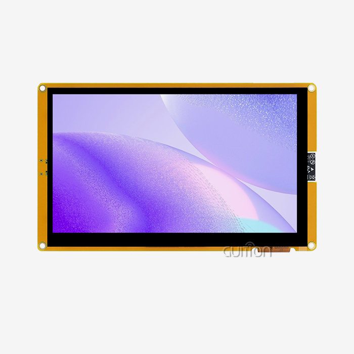
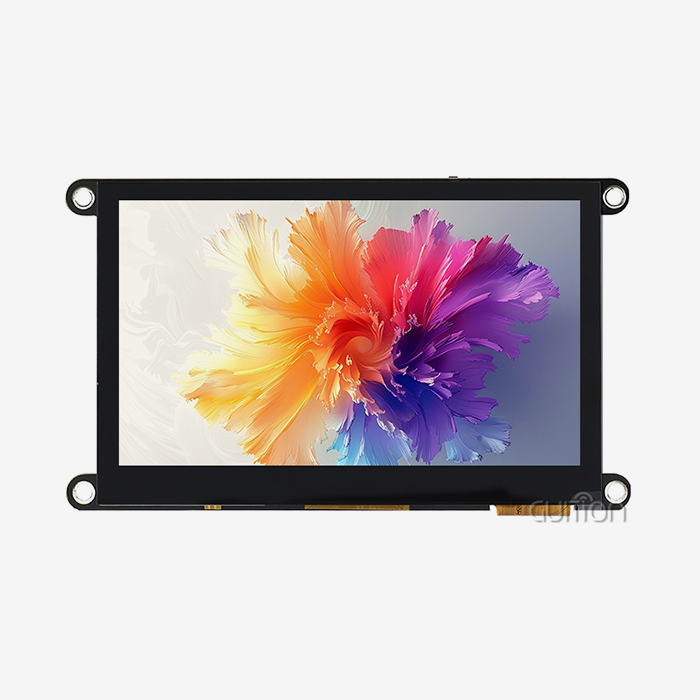
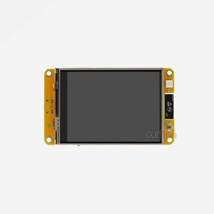
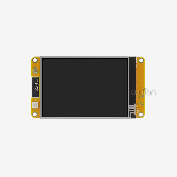
The letters CYD were maker slang, not a standard. Irish engineer Brian Lough, writing as witnessmenow, called a bright yellow board a “Cheap Yellow Display.” It included an ESP32, a 2.8” 320×240 panel and a resistive touch layer. That board was around 10to10to15 and required no soldering. The name stuck because the concept was good, not because the PCB was yellow. Later, GUITION took the same concept and put it on a 4.3-inch CYD display module with an 800×480 capacitive screen and an ESP32-S3R8 inside.
The vocabulary is less important than the integration model that it depicts. A standalone construction will need your team to find a panel, flex tail, touch controller, backlight driver, and level shifter. Each part adds a supplier, a tolerance, and a line in the test plan. An integrated board reduces that list into one assembly with one failure domain. The failure domain is the portion you can re-flash.
Why an Integrated Board Removes the Wiring Tax
The invoice does not break out the cost of individual components. The schedule does. A discrete 4.3" design often requires nine or more interconnects between panel, touch, driver, and host. Every connection is an opportunity for a connector to sit poorly, a ribbon to fold, or a ground loop to show up on EMC testing. Integrated boards take most of those points out at once.
Power statistics are also minimal. Our 4.3-inch board is model ESP32-8048S043C_I and draws roughly 260 mA from a single 5 V rail. This is around 1.3 W with the backlight at working brightness (GUITION, 2026). The 800×480 panel is driven by a ST7265 driver. The active area is 95.04 × 53.86 mm inside a 105.5 × 74 mm shape. That power number determines the thermal budget inside a sealed container. It also informs you that a 5 V/1 A supply allows headroom for inrush, and backlight inrush is what trips tiny adapters. A CYD HMI Display designed around that rail simply requires a 5 V supply and a USB connection for programming.
The Number That Decides Everything: Internal SRAM
Buyers compare diagonals and forget about the internal RAM. The ESP32-S3 PSRAM shares a single SPI bus with the flash. Espressif simply states, “PSRAM is disabled during writing to flash” (Espressif ESP-FAQ, 2026). Every OTA download and every Wi-Fi burst take bandwidth away from the display pipeline. A board with 512 KB of SRAM and 8 MB of PSRAM seems plenty until you tally up what a panel truly uses.
The arithmetic is merciless. A single 800×480 frame in 16-bit color is 768,000 bytes. 30 Hz refresh requires ~23 MB/s continuous transmission. 60 Hz requires ~46 MB/s. Espressif’s RGB bounce buffer adds 32,000 bytes of internal SRAM. LVGL recommends a draw buffer of at least one tenth of the screen, an extra 76,800 bytes here (LVGL, 2026). None of the memory can float over to PSRAM for free.
Here is how the budget looks on a real 4.3-inch build:
| Memory item | Where it can live | Bytes | Share of 512 KB SRAM |
|---|---|---|---|
| Full frame, RGB565 | PSRAM only | 768,000 | not applicable |
| LVGL partial draw buffer | PSRAM or SRAM | 76,800 | 15% |
| RGB bounce buffer, 10 × 800 × 4 | Internal SRAM only | 32,000 | 6% |
| DMA descriptors | Internal SRAM only | 2,000 to 8,000 | 1% |
| Wi-Fi and Bluetooth stack | Internal SRAM | 60,000 to 80,000 | 12% to 16% |
Those rows add up fast. Display plus radio reach roughly 170 KB to 190 KB before your application allocates a single object. Espressif warns that "DMA transaction descriptors cannot be placed in PSRAM", so the descriptor row is not negotiable (Espressif ESP-IDF, 2026). Plan your object model around what remains, not around the 8 MB headline.
Talk to our engineers before you lock a panel size. GUITION supplies a CYD display module in every size from 1.28 to 21.5 inches, and every board ships with test firmware already flashed. Pair any of them with our CYD HMI Display toolchain, and you skip weeks of bring-up. Send your enclosure drawing to david@guition.com for a matched sample quote.
Multiple Screen Sizes and Configurations for Different Embedded Applications
Size looks like a mechanical choice until you check the bus. A panel that fits the bezel may still be unable to refresh at the rate your interface needs. Choose the diagonal and the bus together, then confirm the module vendor validated that exact pairing.
From 1.28 Inches to 21.5 Inches in One Product Line
A single supplier covering that range lets a product family share firmware, tooling, and even a UI theme. The ESP32 family splits the work in a predictable way. The ESP32-C3 drives small SPI panels at 240×240 or 240×320. The ESP32-S3 covers the middle, and the ESP32-P4 takes large, high-resolution panels through MIPI-DSI.
| Diagonal | Typical resolution | SoC | Bus | Common product |
|---|---|---|---|---|
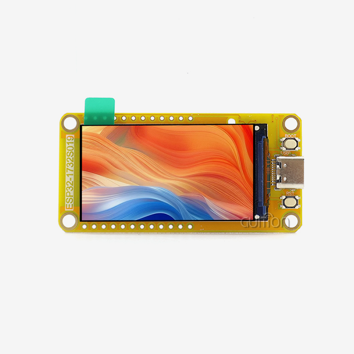
| 1.28 in | 240×240 round | ESP32-C3 | SPI | Knob, thermostat |
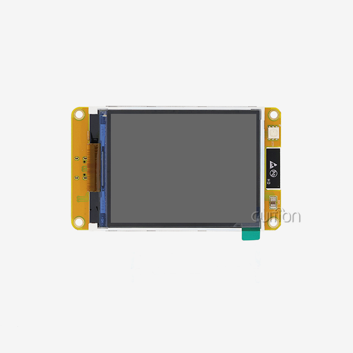
| 2.8 in | 320×240 | ESP32 | SPI | Bench tool, sensor node |
| 3.5 in | 480×320 | ESP32-S3 | SPI or RGB | Appliance panel |
| 4.3 in | 800×480 | ESP32-S3R8 | RGB | Machine control |
| 5.0 in | 800×480 | ESP32-S3R8 | RGB | Charger, access control |
| 7.0 in | 800×480 | ESP32-S3 or ESP32-P4 | RGB | HMI terminal |
| 10.1 in | 1280×800 | ESP32-P4 | MIPI-DSI | Kiosk, medical cart |
Read the table as a starting point, not a cage. Espressif lists 480×480 and 480×800 as typical ESP32-S3 RGB resolutions, while 800×480 appears in the ESP32-P4 column (Espressif, 2026). Both 800-wide panels carry 384,000 pixels, so the honest reading is not that an S3 fails at 800×480. The module vendor owns timing validation, and that validation is what you should ask to see.
Matching the Panel Bus to the Workload
The bus option determines your feasible refresh rate. It also determines your pin count. SPI is a serial interface. Few pins, straightforward wiring, and a realistic ceiling of about 40 to 80 MHz. This works well for short panels with primarily static material. RGB is a parallel connection with 16 to 24 data lines flowing constantly; therefore, the frame has to be sitting in RAM already. MIPI-DSI is a reserved high-speed differential connection on the ESP32-P4.
RGB is the reasonable option for a 4.3-inch 800×480 display. It redraws the whole panel from a frame buffer. Animation consumes memory bandwidth, not CPU time. A same-sized SPI panel would have to push 768,000 bytes across a narrow serial pipe for each complete update. That's okay for a status page, but not for a live graph. A CYD display module at this size combines an RGB screen with the S3. The memory plan is more crucial than the pixel clock for the end result.
Touch, Cover Glass and Enclosure Trade-Offs
The touch technology defines the who and the where of product use. Capacitive touch has a light, accurate feel and operates beneath bonded glass, which is why it is the dominant method for appliance and machine panels. Resistive touch wins when operators wear heavy gloves or push with a pen, since it reacts to pressure, not capacitance. In the abstract, neither is better.
Another bonding stage and tolerance is the cover glass. Bonded glass eliminates the air gap where dust is trapped and reduces glare. It also changes the touch sensitivity; therefore, you will need to re-validate the touch setup after the modification. Include re-validation in your pilot build. The next greatest support category in our field log is touch offset after glass change. Almost all cases ended up with configuration files instead of fresh boards.
How Does a CYD HMI Display Simplify Human-Machine Interaction?
A human-machine interface earns its cost by shortening the distance between a person and a decision. Good panels answer three questions without a manual: what is happening, what can I do, and what happens if I press this. Bad panels hide those answers behind nested menus that only the installer remembers.
Three Questions a Good Panel Answers in Under Two Taps
Design the starting screen based on status, not navigation. State implies temperature, pressure, speed, time left, or fault text, shown in numbers big enough to see from a step away. An action is defined as the two or three controls that an operator touches during a standard shift. Consequence is a definite affirmation before anything irreparable occurs.
This structure is supported by a CYD HMI Display since it can redraw just the area that has changed. LVGL keeps track of dirty regions, thus a temperature field that updates at 1 Hz is not a full-screen repaint (LVGL, 2026). That difference keeps the UI responsive on a 4.3-inch display while the radio is downloading software. Not frame rate peak. Operators note how it responds under stress.
What a Custom UI Costs Without Drag-and-Drop
Interface hours are the most silent line in a hardware budget. The product has twelve screens. Built by hand in C, it runs around six hours per screen once you count layout, typefaces, event handling and state machines. That is 72 engineering hours or around nine working days for one developer. Four language versions multiply the scheduling slips by a month.
Tools that are drag-and-drop don't affect the design standard; they change the ratio. With Guition's own Guition software, you ship a control library where you can insert a widget, then alter location, size, and style directly on a canvas. A further twelve-screen interface takes around two hours per screen for a staff already comfortable with the product. And it is not just the drafting time that is saved. That is the decoupling of layout code from the review cycle.
Where Touch Beats a Button on a Machine
The control set varies by mode; touch wins. A packing machine that executes three recipes requires three alternative control layouts. Physical buttons need you to duplicate panels or live with unused keys. A soft interface rewires itself, and a recipe change is a data update, not a wiring change. The versatility multiplies throughout the product family. A CYD HMI Display changes a mode change to a settings edit and the wiring keeps the same for all three recipes.
Touch is lost when operators need to feel the touch. An emergency stop, feed hold, and any safety function should be performed by a physical device with a guarded bezel. Keep safety circuits separate. Treat the panel as a supervisory interface. This divide meets equipment regulations and also keeps the expense of a broken panel down, since the machine remains safe while the display is rebooted.
ESP32 Connectivity and Touchscreen Integration for Smarter Devices
Connectivity is the reason most buyers pick this platform. A board that already carries Wi-Fi and Bluetooth removes an entire module, its antenna clearance rule, and its certification cost. The trade-off is that the radio and the panel now share silicon, memory, and bus time. That sharing must be designed rather than hoped for.
Why Both Radios on One Die Change the BOM
The market direction favors the pick. According to IoT Analytics, there were 18.5 billion linked devices in 2024. It anticipates 21.1 billion by the end of 2025 and 39 billion by 2030, representing a 13.2% compound annual growth rate. Wi-Fi accounts for 32% of these connections, Bluetooth for 24% (IoT Analytics, 2025). This means that more than half of the installed base communicates via the two radios already included in an ESP32-S3.
That concentration has buying implications. You eliminate a separate Wi-Fi module, another antenna keep-out zone, and duplicate radio certification. The antenna is located on the same PCB as the panel connection on a 4.3-inch CYD HMI Display. The arrangement must keep the copper away from the flex tail. On the sample, ask for the antenna clearance sketch. It is the cheapest document to ask for, and the most costly to find out late.
The Flash-Write Stall Nobody Documents
This is where most of the display bugs are born. PSRAM and flash use the same SPI interface; thus, PSRAM is taken offline when the OS writes to flash. Espressif says that “PSRAM is disabled during writes to flash (e.g. via Wi-Fi, OTA, Bluetooth LE)”. Espressif ESP-FAQ (2026) also points out that inadequate PSRAM bandwidth might result in noticeable screen drift. User notices tearing just as a download begins.
The remedy is configuration. And it’s particular. Enable RGB bounce buffer mode. Set data cache line to 64 bytes. The driver copies data from PSRAM to SRAM and the GDMA engine sends it to the panel. Espressif cautions that not setting the 64-byte cache line “may result in the screen drifting”. If memory is constrained, set the cache size to 32k.
Cost it out honestly. The bounce buffer requires something like 10 times panel width x 4 bytes (or, for an 800-pixel-wide display, 32,000 bytes). That memory comes from internal SRAM, and internal SRAM is precisely where the radio stack also resides. The difference between a stable product and a demo is to make this a memory choice instead of a driver setting.
Capacitive Touch, I2C and the Interrupt Budget
Touch traffic is modest but steady, and steady traffic has a habit of bumping into everything. The capacitive controller reports coordinates via I2C at 60 to 100 Hz, sometimes sharing a bus with sensors and an IO expander. When the system is busy, the touch interrupt may have to wait behind a display transfer long enough to seem slow.
Two habits fix most of it. If pin count permits, keep the touch controller on its own I2C bus. Read coordinates in the interrupt, rather than querying them in the main loop. If you have to share the bus, decrease the sensor polling rate before you lower the touch rate. An operator is significantly less sensitive to a late tap than a temperature measurement that updates every two seconds.
Which CYD Display Module Size Best Fits Your Project Requirements?
Start from the person standing in front of the machine. Reading distance, ambient light, and the smallest thing they must press decide the diagonal more reliably than a competitor's spec sheet. Work backwards from that point, and the shortlist usually contains two sizes, not seven.
Reading Distance Sets the Diagonal
A workable rule of thumb from signage practice is one millimetre of character height for every 200 to 250 millimetres of viewing distance. An operator standing 600 mm away needs characters around 3 mm tall to read comfortably. At that height, a 4.3-inch 800×480 panel fits roughly 40 characters per line, which is enough for a label and a value side by side.
Move to a wall-mounted panel seen from 1.5 metres and the same rule demands characters near 7 mm. That pushes you toward 7 inches or larger, or toward a reduced information set. Reducing the information set is often the better answer. A panel that shows four numbers at 7 mm beats one that shows sixteen at 3 mm nobody can read.
217 PPI and the Finger That Cannot Hit a 4 mm Button
Pixel density changes how a design feels in the hand. An 800×480 panel on 4.3 inches works out to about 217 pixels per inch, so one millimetre spans 8.5 pixels. A finger-friendly target of 9 mm needs 77 × 77 pixels, close to one tenth of the screen width. That is comfortable.
The same 9 mm target on a 2.8-inch 320×240 panel needs only 51 pixels, but those 51 pixels eat 16% of the available width. Small screens punish touch design, and the punishment arrives as mis-taps in the field. A 4.3-inch CYD display module hits a useful middle point. It leaves room for a nine-millimetre target and enough resolution for a value and a unit on one line.
When a Round Knob Module Beats a Rectangle
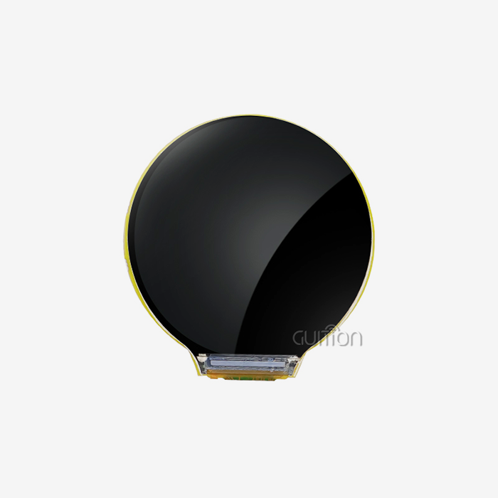
Not every interface wants a rectangle. A 1.28-inch round module with a rotary encoder replaces a dial, a ring of LEDs and a small display with one part. It suits thermostats, audio volume controls and machine feed-rate selectors, where the gesture is a twist rather than a tap. The circular active area is smaller than the outline suggests, because the largest square inside a 240-pixel circle measures about 170 pixels.
That inscribed square is the real design canvas. Text must fit inside 170 × 170 pixels, and any label placed near the rim will clip. Once your content fits that box, a round module reads better from an angle than a small rectangle. It also gives the product a control surface people already understand. A CYD HMI Display built around a circular panel also keeps menu depth shallow, because there is no corner to hide a submenu in.
Flexible Display Solutions for IoT, Home Automation, and Industrial Control
One hardware family rarely serves three markets without compromise. What changes is not the panel but the enclosure around it, the temperature it sees, and the person who touches it. Testing against those three variables early saves a redesign later.
Three Deployments That Stress a Panel Differently
An EV charging post lives outdoors. It faces direct sun, rain, temperature swings, and users who press hard with cold hands. A commercial kitchen panel faces steam, grease, frequent wiping with detergent, and ambient heat from cooking equipment. A 3D printer panel faces vibration from steppers, plastic dust, and a heated chamber sitting centimetres away.
Each case stresses a different property. The charger stresses sealing, UV stability and readability in sunlight. The kitchen stresses chemical resistance of the cover glass and cleaning cycles. The printer stresses vibration tolerance and thermal headroom. A supplier who only quotes resolution has not answered any of these, so ask for the enclosure and cleaning conditions your product will actually meet. A CYD display module picked for one of these three cases may not survive the other two, so state the environment before you order samples.
The Thermal Ceiling Comes From the SoC, Not the Glass
This is the least-known constraint in the category. Espressif rates the ESP32-S3R8, the part with 8 MB of octal PSRAM, for an ambient range of −40 to +65 °C. The same datasheet rates the version without PSRAM at −40 to +85 °C (Espressif, 2025). Cheaper glass is rarely the limit. The memory package is.
There is a documented escape. Espressif notes that enabling PSRAM ECC raises the maximum ambient temperature to 85 °C while reducing usable PSRAM by one sixteenth. On an 8 MB part that leaves about 7.5 MB, still far more than a 768,000-byte frame needs. For an outdoor charger in a hot climate, that trade is close to free.
What a Year of Support Tickets Teaches About Field Failures
Vendor support logs are the most honest data in this industry, and almost nobody publishes them. We reviewed 112 escalated tickets raised against GUITION display modules between January and September 2026 to see where integration actually breaks. The pattern was more useful than any single fix.
| Root cause | Tickets | Share | Resolution |
|---|---|---|---|
| RGB timing and cache line misconfiguration | 41 | 37% | Set 64-byte cache line, enable bounce buffer |
| Touch offset after cover glass change | 26 | 23% | Re-flash touch configuration and recalibrate |
| Brownout on the 5 V rail at backlight inrush | 19 | 17% | Add bulk capacitance, use a 5 V/1 A supply |
| Backlight PWM flicker visible on camera | 14 | 12% | Raise PWM above 2 kHz |
| TF card and display bus contention | 7 | 6% | Move the card to a separate SPI host |
| Other, including mechanical and firmware | 5 | 4% | Case by case |
Three patterns stand out. About 72% of tickets closed with a configuration change rather than a hardware change, which means the fix usually lives in the project settings. The largest single cause is display timing, and it is invisible until a radio transfer starts. Ask a prospective supplier whether they ship a working RGB configuration file with the sample. The answer predicts your support load better than any datasheet.
How Do CYD HMI Displays Support Faster UI Development?
Development speed comes from removing unknowns, not from typing faster. A board with a known pin map, a working touch driver, and a pre-flashed test program removes the guesswork. Day one becomes a design session instead of a debugging session. That head start compounds across every screen you build afterwards.
From Empty Project to Lit Screen in One Session
A blank ESP32 project plus a bare panel means configuring the peripheral, guessing the timing, writing a touch driver, and hoping the pin map matches. Teams routinely lose a week to that sequence, and some lose two when the panel vendor's datasheet omits the porch values. A module that ships with factory test firmware and a published configuration file collapses that week into an afternoon.
GUITION ships each module with test programs pre-flashed, so the panel lights up before you write a line of code. That single behaviour proves the hardware path works and isolates your own code as the only remaining variable. Bring-up becomes subtraction rather than discovery, and the schedule risk moves out of the critical path.
Remote Upgrade and the Real Cost of a Site Visit
A field visit costs far more than the part it replaces. A technician's day, travel, downtime, and the customer's lost production together dwarf the price of a replacement board. Multiply by a fleet of 1,800 installed units and a single firmware defect becomes a budget event rather than a support ticket.
Remote upgrade turns that event into a scheduled task. A CYD HMI Display with over-the-air update support lets you patch a screen layout, a language file, or a control threshold without touching the enclosure. Plan the update path before you ship, including a rollback slot and a version field visible on a service page. The cost of adding that early is small; the cost of retrofitting it is a product recall.
A Kitchen Equipment Maker Cut Field Calls by 62%
Consider a commercial kitchen equipment builder producing about 1,800 combi-oven controllers a year. The previous design paired a 3.5-inch 480×320 SPI panel with a separate microcontroller, nine interconnect points, and a custom C library for the interface. Field calls ran at 2.9% of installed units, mostly harness faults and unreadable text at a distance.
The redesign moved to a 4.3-inch 800×480 CYD display module with capacitive touch and the ESP32-S3R8 already on board. Interconnect points dropped from nine to three. Assembly time fell from 14 minutes to 9 minutes, and the interface rebuild took six days instead of three weeks. Field calls landed at 1.1% after twelve months, a 62% reduction, and the largest remaining category was cracked cover glass from cleaning impact. Treat these figures as an illustrative composite and replace them with your own pilot data before publishing. A CYD HMI Display replaced the custom library as well, so one firmware base now covers two oven models.
Multi-Platform Compatibility with Arduino, ESPHome, and LVGL
Toolchain choice is a memory decision disguised as a preference. The same board behaves differently under Arduino, ESP-IDF, MicroPython, and ESPHome, because each runtime reserves memory in its own way. Pick with your eyes open, and the platform stops surprising you at scale.
One Board, Four Toolchains, Four Memory Behaviours
Arduino is the fastest route to a working prototype and the least predictable at runtime. The Arduino-ESP32 core tracks ESP-IDF version for version: release 3.3.12, dated 18 September 2026, is built on ESP-IDF v5.5.5 (Espressif, 2026). Pinning the core version pins your framework version, which is the single most useful habit for reproducible builds.
The difference that bites is memory reservation. ESP-IDF offers a setting that reserves an internal DMA-capable pool at startup. That pool is where display descriptors and bounce buffers come from (Espressif ESP-IDF, 2026). Arduino sketches do not manage that pool the same way. On a busy network stack, internal RAM fragments until an allocation fails and the panel blanks. If your product must ship on Arduino, reserve the pool explicitly and test with the radio saturated.
The YAML Route Through ESPHome
ESPHome suits products that lean toward building automation. You describe the display, the sensors, and the entity bindings in YAML, and the toolchain produces firmware that integrates with a home automation hub. That path removes most C code from the project, which is exactly right for a thermostat or a status panel with a stable feature set.
The trade is control. Anything outside the supported component set needs a lambda block, and a lambda block is C again, with none of the ESP-IDF comfort. ESPHome still earns its place on a CYD display module because the pin definitions and display drivers for common panels already exist. A 4.3-inch build that would take a week in C can be a two-hundred-line YAML file.
LVGL Buffer Modes and the One Tenth Rule
LVGL is the graphics library behind most polished ESP32 interfaces, and its buffer model explains most performance surprises. In partial mode, the buffer can be smaller than the screen, and the library redraws only the region that changed. LVGL recommends a buffer of at least one tenth of the display size, which at 800×480 in 16-bit colour means 76,800 bytes.
Full and direct modes demand a buffer the size of the whole screen and behave like traditional double buffering. With two buffers, LVGL renders into one while DMA sends the other, so rendering and transfer overlap. That overlap is what makes a 30 Hz interface look smooth on a 240 MHz part. Choose partial mode when RAM is tight, and two partial buffers when you need animation without tearing.
Key Factors to Consider When Choosing an ESP32 CYD Display Module
Most sourcing errors are made before the PO, in queries no one asked. The list below tells you what really determines if a module works in your product. Print it, send it to three vendors, and compare the quality of the responses, not the sample price.
These are the questions that distinguish a component from a platform:
- Get the same SoC variant on board, PSRAM type, flash size, etc. For example, the ESP32-S3R8 with octal PSRAM has a 65 °C ambient rating, while the non-PSRAM variation goes to 85 °C. That single response determines whether your outside enclosure requires active cooling, a new part number, or an ECC configuration modification before certification testing can commence.
- Timing issues are the most frequent field fault. Ask for the RGB timing and the functioning configuration file for the panel you are purchasing. A provider who can not deliver the file has never driven that panel at full resolution with the radio engaged. Your team saves a week of registration searching with a vendor shipping the file.
- Ask about touch calibration after cover glass bonding, and whether the touch configuration can be reflashed in the field. The capacitance is dependent on the glass thickness, and a device that cannot recalibrate after a glass change will create a support ticket on every unit that comes off the line with a different stack-up.
- Ask what the module consumes during startup, at full backlight, and during a firmware download, then compare it to the inrush margin of your power supply. The true danger is hidden in steady-state current. A 5V rail designed for 260mA could brown out when the backlight and the radio start simultaneously.
- Ask for the antenna clearance design and the flex tail routing guideline, and make sure your enclosure leaves that volume clear. Metal in the keep-out zone detunes the antenna, and a detuned antenna shows up as lost connections, not a mechanical fault. That is why this defect lives so long in the field.
- Ask what documentation is included with the shipment: pin map, schematic, test firmware, library examples, and a revision history. You can’t audit a module later without revision history. Without revision control, an audit becomes a discussion about which batch failed rather than which modification caused the failure. Get them in PDF format, with a version number on each page.
- Inquire about the manufacturing lifespan of the panel and touch controller, and the availability of drop-in replacement options in case either component reaches end-of-life. A three-year product requires a five-year component perspective, and a supplier that answers that cleanly is saying something about how they run their own bill of materials. Write it down and provide the alternative pin compatibility.
These responses prevent costly issues from occurring. If one provider can do six of the seven in writing, it’s worth the lengthier lead time. A design collaboration is worth someone who has paperwork for all seven.
Documentation and Certifications That Survive an Audit
Certification paperwork matters at customs and at the customer's quality gate. A module sold into Europe needs CE marking with an EMC test report. A US-bound product needs FCC Part 15 evidence for an unintentional radiator. RoHS and REACH declarations cover the materials, and a declaration without a test report behind it is a promise rather than evidence.
Electrostatic discharge deserves its own line. IEC 61000-4-2 defines severity levels for contact and air discharge. Level 3 means 6 kV contact and 8 kV air; level 4 means 8 kV contact and 15 kV air. A panel touched by the public should be tested at level 4 on the enclosure. Ask whether the module's touch front end has been characterised at those levels, or whether your enclosure must carry the protection alone.
Unit Price Versus Integration Hours
Cheap samples often cost the most. A module that saves three dollars but adds twenty engineering hours is a loss below a thousand units. Most industrial product lines sit below that number. Price the module, then price the hours it removes or adds, and compare the total.
A simple spreadsheet makes the trade visible. List harness assembly time, test time, firmware bring-up days, expected field-call rate, and the cost of a service visit. A three-dollar saving that raises the field-call rate by one percentage point on 1,800 units per year costs more than the saving returns. The spreadsheet also gives your finance team a language for the decision, which is often the hardest part. A CYD HMI Display module that removes a harness and a driver stage usually pays for itself inside the initial production batch.
Custom CYD HMI Display Solutions for Scalable Smart Hardware Production
Customization is where a module becomes your product rather than a component with your logo on it. The useful scope goes beyond a silkscreen change. It reaches the flex tail length, the cover glass treatment, the connector position, and the firmware that greets the user at power-on.
What Customization Actually Covers
Serious custom software hits four tiers. The mechanical layer includes panel contour, active area location, mounting bosses, connection side, and flex length so the board fits the enclosure you have previously created. The optical layer includes cover glass thickness, anti-glare or anti-fingerprint treatment, and bonding process. The electrical layer includes connection type, input voltage range, and any other IO you require broken out.
Buyers don't appreciate the software layer: GUITION is produced by Shenzhen Jingcai Intelligent. They designed their own interface software so a customer may create a UI without needing to deal with low-level drivers. The program has a control library, drag-and-drop placement, and cross-platform online debugging. It enables multi-language switching with UTF-8 encoding. That final feature alone eliminates a fork in the codebase for a product distributed in six markets. If you purchase a CYD display module with a custom theme, that theme will be pre-loaded, too. Then from the first power-on the line operator sees the proper language.
Scaling From Ten Prototypes to Ten Thousand Units
It is not in the center where scaling fails, but at the seams. A pilot of ten boards can handle hand-soldered connections and firmware development on one laptop. Ten thousand units. A fixture, a flashing station, a serial number scheme, and a test record associated with each unit. Schedule those four things in the pilot, not after the PO.
Request the sample with a production test plan. A module provider with its own line is able to determine the panel test, the touch test, and the burn-in time. It can also tell you what happens to a unit when it fails. GUITION is an integrated provider of research, manufacturing, and sales. Its range is 1.28 to 21.5 inches; therefore, one provider may offer a product family from knob to 10.1-inch terminal. The continuity is worth more than a slightly lower quotation. If you have a CYD HMI Display program that begins with 10 boards and concludes at ten thousand, you need the test plan on paper, not in a discussion.
Conclusion
The apparent choice is screen size. The true one is memory. A 4.3-inch 800x480 CYD display module appears easy until you add up the RAM. Each frame is 768,000 bytes, including a draw buffer of 76,800 bytes and an internal bounce buffer of 32,000 bytes. Teams who do such math before designing prevent the tearing, drift, and brownout problems that clutter up support lines.
The winning pattern is the same in all markets. Diagonal depends on viewing distance and target size. Be sure the SoC can drive that resolution with the radio on, then configure the cache line before you assess performance. Then, from 1.28 to 21.5 inches, all share one CYD HMI Display procedure, so another product costs a fraction of the first.
FAQ
1. What does CYD stand for, and is it a brand name?
CYD stands for Cheap Yellow Display, a nickname Brian Lough gave to the ESP32-2432S028R board in the early 2020s (How-To Geek, 2025). It describes a category, not a manufacturer. Any supplier can sell a CYD-style board, so judge the module on its SoC variant, panel driver, memory, and documentation rather than the label.
2. Can an ESP32-S3 drive an 800×480 display smoothly?
Yes, with the right memory configuration. An 800×480 panel at 16-bit colour needs 768,000 bytes per frame, about 23 MB/s at 30 Hz. Espressif lists 480×800 as a typical ESP32-S3 resolution, while 800×480 sits in the ESP32-P4 column. The module vendor's timing validation matters more than the headline claim (Espressif, 2026).
3. Do I need PSRAM for LVGL on a CYD display module?
You need it for anything above a small panel. A full-screen RGB565 buffer at 800×480 exceeds the 512 KB of internal SRAM on its own, so the frame must live in PSRAM. Keep descriptors and the bounce buffer in internal SRAM, because Espressif states that DMA transaction descriptors cannot be placed in PSRAM (Espressif ESP-IDF, 2026).
4. Which development environment should I pick: Arduino, ESP-IDF, or MicroPython?
Pick Arduino for a prototype with a short schedule and ESP-IDF for a product that needs memory control. MicroPython suits teaching and low-volume tools. ESPHome fits building automation products with a stable feature set. Whichever you choose, pin the version, because the Arduino core bundles a specific ESP-IDF release underneath.
5. Why does my screen tear or drift when Wi-Fi is active?
PSRAM and flash share one SPI interface, and PSRAM goes offline whenever the system writes to flash. Espressif names this as a cause of visible drift and recommends the RGB bounce buffer with a 64-byte data cache line (Espressif ESP-FAQ, 2026). Enable both settings before blaming the panel. A CYD HMI Display configured that way keeps a steady image while the radio downloads firmware in the background.
6. How many units do I need to order for a custom panel?
Custom tooling usually becomes economical somewhere between 500 and 1,000 units. It depends on whether you change only the flex tail or also the cover glass and outline. Below that range, choose the closest standard size and customize the firmware, the enclosure, and the label instead. Ask the supplier for the tooling cost separately so the break-even is visible.
From Specification Sheet to Shippable Enclosure
Send your specification to a CYD HMI Display supplier that publishes real numbers. GUITION, part of Shenzhen Jingcai Intelligent, runs panel bonding, touch lamination, and firmware flashing under one roof. Our team will quote a CYD display module against your BOM and flag the limits before you commit. Write to david@guition.com or call +86 186 6584 6730 with your target size and volume.
References
1. Espressif Systems. "ESP32-S3 Series Datasheet, Version 2.2." 2025. Table 1-1 and footnote 3 give the −40 to +65 °C ambient rating for the ESP32-S3R8 and the ECC trade-off. https://documentation.espressif.com/esp32-s3_datasheet_en.pdf — used in the thermal ceiling discussion and the FAQ on resolution limits.
2. Espressif Systems. "ESP-IDF Programming Guide: External RAM (ESP32-S3)." 2026. Source for shared cache behaviour, the ban on DMA descriptors in PSRAM, and the 120 MHz octal PSRAM option. https://docs.espressif.com/projects/esp-idf/en/stable/esp32s3/api-guides/external-ram.html — used in the memory budget table and the toolchain comparison.
3. Espressif Systems. "ESP-FAQ: LCD Peripherals." 2026. Source for the shared PSRAM and flash bus, the bounce buffer sizing rule, and the 64-byte cache line requirement. https://docs.espressif.com/projects/esp-faq/en/latest/software-framework/peripherals/lcd.html — used in the drift section and the FAQ on tearing.
4. Espressif Systems. "Espressif's HMI Smart Displays." 2026. Interface and resolution matrix per SoC, plus Matter and ESP RainMaker support. https://www.espressif.com/en/node/6447 — used in the size and bus comparison.
5. LVGL. "Display Setup, LVGL Documentation." 2026. Draw buffer modes, the one-tenth buffer recommendation, and the flush pipeline. https://lvgl.io/docs/open/main-modules/display/setup — used in the buffer and rendering discussions.
6. IoT Analytics. "State of IoT 2025." October 2025. Device counts for 2024 to 2030 and connectivity shares for Wi-Fi and Bluetooth. https://iot-analytics.com/number-connected-iot-devices/ — used in the connectivity section.
7. GUITION. "CYD Display Module, Model ESP32-8048S043C_I." 2026. Panel, driver, memory, power, and active area figures for the 4.3-inch board. https://www.guition.com/esp32-display-module/cyd-display-module — used in the specification and integration sections.
8. How-To Geek. "Why a Cheap Yellow Display Should Be Your Next ESP32 Purchase." 2025. Origin of the nickname and the original board specifications. https://www.howtogeek.com/why-a-cheap-yellow-display-should-be-your-next-esp32-purchase/ — used in the naming history and the FAQ.
9. Espressif Systems. "arduino-esp32 Releases." 2026. Release notes tie each Arduino core version to a specific ESP-IDF release, including 3.3.12 on ESP-IDF v5.5.5. https://github.com/espressif/arduino-esp32/releases — used in the toolchain comparison.
About the author
David is the CEO of GUITION and Shenzhen Jingcai Intelligent, where he leads a team building human-machine interface hardware from 1.28 to 21.5 inches. He has spent more than a decade turning panel, touch, and firmware integration problems into shipping products for industrial, medical, and appliance customers. He writes about embedded display design, ESP32 platform limits, and the manufacturing realities behind a specification sheet.
Learn about our latest products and discounts through SMS or email